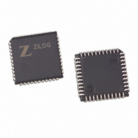
Z85C3008VSG Zilog, Z85C3008VSG Datasheet - Page 203

Z85C3008VSG
Manufacturer Part Number
Z85C3008VSG
Description
IC 8MHZ Z8500 CMOS SCC 44-PLCC
Manufacturer
Zilog
Series
SCCr
Specifications of Z85C3008VSG
Processor Type
Z80
Features
Error Detection and Multiprotocol Support
Speed
8MHz
Voltage
5V
Mounting Type
Surface Mount
Package / Case
44-LCC (J-Lead)
Maximum Operating Temperature
+ 70 C
Minimum Operating Temperature
0 C
Mounting Style
SMD/SMT
Cpu Speed
8MHz
Digital Ic Case Style
LCC
No. Of Pins
44
Supply Voltage Range
5V
Operating Temperature Range
0°C To +70°C
Svhc
No SVHC (18-Jun-2010)
Base Number
85
Rohs Compliant
Yes
Clock Frequency
8MHz
Lead Free Status / RoHS Status
Lead free / RoHS Compliant
Other names
269-3932
Z85C3008VSG
Z85C3008VSG
Available stocks
Company
Part Number
Manufacturer
Quantity
Price
Company:
Part Number:
Z85C3008VSG
Manufacturer:
Zilog
Quantity:
800
Company:
Part Number:
Z85C3008VSG
Manufacturer:
MAX
Quantity:
74
- Current page: 203 of 317
- Download datasheet (4Mb)
Application Note
The Zilog Datacom Family with the 80186 CPU
While the ESCC and ISCC can drive their Baud Rate
Generators from their PCLK inputs, the IUSC cannot do
this from its CLK input. The 80186 clock output SYSCLK is
brought to pins 7 of J9, J10, and J12 at which point it can
be jumpered to pin 9 or 8 so that it is routed to the /TxC or
/RxC pin of the device.
SERIAL INTERFACING
The serial I/O pins of the four serial controllers are
connected to the six connector blocks labelled J5 through
J10. In addition, the port pins of the IUSC are connected to
the J11 connector block, and the port pins of an MUSC or
the B channel of a USC are connected to J12. These
connector blocks can be interconnected for communication
between on-board serial controllers, or they can be
connected to the user’s custom communications hardware
on another board. As a third option, they can be connected
to three on-board serial interfaces via the connector blocks
labelled J13 through J15.
Two of the on-board serial interfaces use EIA-RS-232
signal levels and pin arrangement. 25-pin D connectors
J1A or J2A are configured as DTE, while J1B and J2B are
configured as DCE. These serial interfaces are used by
6-68
IUSC (Continued)
Starting Addr
(PBA)+512
(PBA)+576
(PBA)+640
(PBA)+704
(PBA)+768
(PBA)+832
To use the following serial controller channel
with off-board or on-board serial hardware:
(E)SCC Channel A
(E)SCC Channel B
ISCC Channel A
ISCC Channel B
IUSC
(M)USC
Ending Addr
(PBA)+575
(PBA)+639
(PBA)+703
(PBA)+767
(PBA)+831
(PBA)+895
Table 7. Controller Port Connectors
Since the IUSC contains its own DMA channels, its
/RxREQ and /TxREQ pins have no dedicated function.
They can be used for Request to Send and Data Terminal
Ready; the two signals are lightly pulled up to allow for the
fact that they are not driven after Reset.
connecting one of J5-J10 to J13 or J14, respectively. J1B
is typically used for connection to the user’s PC or
terminal.
The third on-board serial interface uses EIA-422 signal
levels on connector J3A,J3B, or J4, and is used by
connecting one of J5-J10 to J15. The 25-pin D connector
J3A uses the DTE pin arrangement put forth in the EIA-530
standard. J3B is a DCE version of EIA-530, while the 8-pin
circular DIN connector, J4, is compatible with the Apple
Macintosh Plus and later Macintoshes, and thus with
AppleTalk/LocalTalk equipment.
The serial interface connectors are summarized in the
following tables:
Registers Accessed
16-bit access to IUSC Transmit DMA registers
8-bit access to IUSC Transmit DMA registers
16-bit access to IUSC Receive DMA registers
8-bit access to IUSC Receive DMA registers
16-bit access to IUSC Serial Controller registers
8-bit access to IUSC Serial Controller registers
Connect to this (these) 10-pin
connector block(s):
J5
J6
J7
J8
J9 (J11 for Port pins)
J10 (J12 for MUSC Port pins
or USC channel B)
UM010901-0601
Related parts for Z85C3008VSG
Image
Part Number
Description
Manufacturer
Datasheet
Request
R

Part Number:
Description:
Manufacturer:
Zilog, Inc.
Datasheet:

Part Number:
Description:
Cmos Scc Serial Communications Controller
Manufacturer:
ZiLOG Semiconductor
Datasheet:

Part Number:
Description:
Communication Controllers, ZILOG INTELLIGENT PERIPHERAL CONTROLLER (ZIP)
Manufacturer:
Zilog, Inc.
Datasheet:

Part Number:
Description:
KIT DEV FOR Z8 ENCORE 16K TO 64K
Manufacturer:
Zilog
Datasheet:

Part Number:
Description:
KIT DEV Z8 ENCORE XP 28-PIN
Manufacturer:
Zilog
Datasheet:

Part Number:
Description:
DEV KIT FOR Z8 ENCORE 8K/4K
Manufacturer:
Zilog
Datasheet:

Part Number:
Description:
KIT DEV Z8 ENCORE XP 28-PIN
Manufacturer:
Zilog
Datasheet:

Part Number:
Description:
DEV KIT FOR Z8 ENCORE 4K TO 8K
Manufacturer:
Zilog
Datasheet:

Part Number:
Description:
CMOS Z8 microcontroller. ROM 16 Kbytes, RAM 256 bytes, speed 16 MHz, 32 lines I/O, 3.0V to 5.5V
Manufacturer:
Zilog, Inc.
Datasheet:

Part Number:
Description:
Low-cost microcontroller. 512 bytes ROM, 61 bytes RAM, 8 MHz
Manufacturer:
Zilog, Inc.
Datasheet:

Part Number:
Description:
Z8 4K OTP Microcontroller
Manufacturer:
Zilog, Inc.
Datasheet:

Part Number:
Description:
CMOS SUPER8 ROMLESS MCU
Manufacturer:
Zilog, Inc.
Datasheet:

Part Number:
Description:
SL1866 CMOSZ8 OTP Microcontroller
Manufacturer:
Zilog, Inc.
Datasheet:


