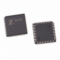
Z85C3008VSG Zilog, Z85C3008VSG Datasheet - Page 60

Z85C3008VSG
Manufacturer Part Number
Z85C3008VSG
Description
IC 8MHZ Z8500 CMOS SCC 44-PLCC
Manufacturer
Zilog
Series
SCCr
Specifications of Z85C3008VSG
Processor Type
Z80
Features
Error Detection and Multiprotocol Support
Speed
8MHz
Voltage
5V
Mounting Type
Surface Mount
Package / Case
44-LCC (J-Lead)
Maximum Operating Temperature
+ 70 C
Minimum Operating Temperature
0 C
Mounting Style
SMD/SMT
Cpu Speed
8MHz
Digital Ic Case Style
LCC
No. Of Pins
44
Supply Voltage Range
5V
Operating Temperature Range
0°C To +70°C
Svhc
No SVHC (18-Jun-2010)
Base Number
85
Rohs Compliant
Yes
Clock Frequency
8MHz
Lead Free Status / RoHS Status
Lead free / RoHS Compliant
Other names
269-3932
Z85C3008VSG
Z85C3008VSG
Available stocks
Company
Part Number
Manufacturer
Quantity
Price
Company:
Part Number:
Z85C3008VSG
Manufacturer:
Zilog
Quantity:
800
Company:
Part Number:
Z85C3008VSG
Manufacturer:
MAX
Quantity:
74
- Current page: 60 of 317
- Download datasheet (4Mb)
UM010901-0601
2.6 TEST FUNCTIONS
The SCC contains two other features useful for diagnostic
purposes, controlled by bits in WR14. They are Local
Loopback and Auto Echo.
2.6.1 Local Loopback
Local Loopback is selected when WR14 bit D4 is set to 1.
In this mode, the output of the transmitter is internally con-
nected to the input of the receiver. At the same time, the
TxD pin remains connected to the transmitter. In this
mode, the /DCD pin is ignored as a receive enable and the
/CTS pin is ignored as a transmitter enable even if the Auto
Enable mode has been selected. Note that the DPLL input
is connected to the RxD pin, not to the input of the receiver.
This precludes the use of the DPLL in Local Loopback. Lo-
cal Loopback is shown schematically in Figure 2-35.
/DCD
RxD
/CTS
TxD
NC
Figure 2-35. Local Loopback
Local Loop Back
Rx Enable
Tx Enable
Transmitter
Receiver
Receiver
2.6.2 Auto Echo
Auto Echo is selected when bit D3 of WR14 is set to 1. In
this mode, the TxD pin is connected directly to the RxD pin,
and the receiver input is connected to the RxD pin. In this
mode, the /CTS pin is ignored as a transmitter enable and
the output of the transmitter does not connect to anything.
If both the Local Loopback and Auto Echo bits are set to 1,
the Auto Echo mode is selected, but both the /CTS pin and
/DCD pin are ignored as auto enables. This should not be
considered a normal operating mode (Figure 2-36).
/DCD
/CTS
RxD
TxD
Figure 2-36. Auto Echo
Auto Echo
SCC™/ESCC™ User’s Manual
Interfacing the SCC/ESCC
NC
Rx Enable
Tx Enable
Transmitter
Receiver
2-41
2
Related parts for Z85C3008VSG
Image
Part Number
Description
Manufacturer
Datasheet
Request
R

Part Number:
Description:
Manufacturer:
Zilog, Inc.
Datasheet:

Part Number:
Description:
Cmos Scc Serial Communications Controller
Manufacturer:
ZiLOG Semiconductor
Datasheet:

Part Number:
Description:
Communication Controllers, ZILOG INTELLIGENT PERIPHERAL CONTROLLER (ZIP)
Manufacturer:
Zilog, Inc.
Datasheet:

Part Number:
Description:
KIT DEV FOR Z8 ENCORE 16K TO 64K
Manufacturer:
Zilog
Datasheet:

Part Number:
Description:
KIT DEV Z8 ENCORE XP 28-PIN
Manufacturer:
Zilog
Datasheet:

Part Number:
Description:
DEV KIT FOR Z8 ENCORE 8K/4K
Manufacturer:
Zilog
Datasheet:

Part Number:
Description:
KIT DEV Z8 ENCORE XP 28-PIN
Manufacturer:
Zilog
Datasheet:

Part Number:
Description:
DEV KIT FOR Z8 ENCORE 4K TO 8K
Manufacturer:
Zilog
Datasheet:

Part Number:
Description:
CMOS Z8 microcontroller. ROM 16 Kbytes, RAM 256 bytes, speed 16 MHz, 32 lines I/O, 3.0V to 5.5V
Manufacturer:
Zilog, Inc.
Datasheet:

Part Number:
Description:
Low-cost microcontroller. 512 bytes ROM, 61 bytes RAM, 8 MHz
Manufacturer:
Zilog, Inc.
Datasheet:

Part Number:
Description:
Z8 4K OTP Microcontroller
Manufacturer:
Zilog, Inc.
Datasheet:

Part Number:
Description:
CMOS SUPER8 ROMLESS MCU
Manufacturer:
Zilog, Inc.
Datasheet:

Part Number:
Description:
SL1866 CMOSZ8 OTP Microcontroller
Manufacturer:
Zilog, Inc.
Datasheet:


