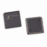
Z85C3008VSG Zilog, Z85C3008VSG Datasheet - Page 234

Z85C3008VSG
Manufacturer Part Number
Z85C3008VSG
Description
IC 8MHZ Z8500 CMOS SCC 44-PLCC
Manufacturer
Zilog
Series
SCCr
Specifications of Z85C3008VSG
Processor Type
Z80
Features
Error Detection and Multiprotocol Support
Speed
8MHz
Voltage
5V
Mounting Type
Surface Mount
Package / Case
44-LCC (J-Lead)
Maximum Operating Temperature
+ 70 C
Minimum Operating Temperature
0 C
Mounting Style
SMD/SMT
Cpu Speed
8MHz
Digital Ic Case Style
LCC
No. Of Pins
44
Supply Voltage Range
5V
Operating Temperature Range
0°C To +70°C
Svhc
No SVHC (18-Jun-2010)
Base Number
85
Rohs Compliant
Yes
Clock Frequency
8MHz
Lead Free Status / RoHS Status
Lead free / RoHS Compliant
Other names
269-3932
Z85C3008VSG
Z85C3008VSG
Available stocks
Company
Part Number
Manufacturer
Quantity
Price
Company:
Part Number:
Z85C3008VSG
Manufacturer:
Zilog
Quantity:
800
Company:
Part Number:
Z85C3008VSG
Manufacturer:
MAX
Quantity:
74
- Current page: 234 of 317
- Download datasheet (4Mb)
UM010901-0601
Notes on Figure 3:
1. The receiver is usually in hunt mode when waiting for
2. The /SYNC output follows the state of the sync register
3. A Receive Character Available Interrupt is generated
4. If SCC’s DMA request function has been enabled,
5. DMA request for data 42H.
6. DMA request for data 0FFH.
7. DMA request for data 42H.
8. DMA request for the first CRC byte. The SCC treats
9. DMA request for the second CRC byte. The closing
a frame. When the opening flag is received, an
External/Status Interrupt is generated, indicating the
change from hunt mode to sync mode.
comparison output. The comparison is done on a bit
by bit basis, so the /SYNC pin is only active for one bit-
time. /SYNC goes active one bit-time after the last bit
of the sync character is sampled at the RxD pin.
11 bit-times after the last bit of the character is
sampled at the RxD pin. In this mode, enable the DMA
on this interrupt. This interrupt is for data 81H.
/REQ becomes active here.
the CRC as data, since the SCC does not yet
distinguish a difference between CRC and data!
flag is recognized two bit-times before the second
CRC byte is completely assembled in the Receive
Shift Register. As soon as it is transferred to the
Receive Buffer, it generates a DMA request.
Serial Communication Controller (SCC
10. This interrupt is EOF (End of Frame), a Special
11. DMA request for 2nd CRC bytes. This occurs when
12. External/Status Interrupt for the Sync/Hunt change.
Condition interrupt. This will not occur until the DMA
has read the 2nd CRC byte from the Receive Buffer.
When it occurs, the Receive Buffer is locked and no
more DMA requests can be generated until the
Receive Buffer is unlocked by issuing the Error Reset
command. Before issuing this command, all of the
status bits required (e.g., the CRC error status) must
be read, and the last two bytes read by the DMA
discarded. The enable interrupt on next Receive
Character command must be sent to the SCC so that
the next character (i.e., the First Character of the next
frame) will produce an interrupt. If this is not done, the
character will generate a DMA request, not an
interrupt.
Should a Special Condition occur within the data
stream (i.e., for a condition other than EOF) the /INT
pin will not go active until the character with the
Special Condition has been read by the DMA.
the EOF interrupt service routine has not disabled the
DMA function of the SCC, and did not read the data
after unlocking the buffer by issuing an Error Reset
command.
This occurs when the SCC recognizes an Abort
(Marking line) and forces the receiver into hunt mode.
The SCC can be programmed so that the Abort itself
generates an interrupt if required. If flag idle was set,
this interrupt would not occur.
™
): SDLC Mode of Operation
Application Note
6-99
1
Related parts for Z85C3008VSG
Image
Part Number
Description
Manufacturer
Datasheet
Request
R

Part Number:
Description:
Manufacturer:
Zilog, Inc.
Datasheet:

Part Number:
Description:
Cmos Scc Serial Communications Controller
Manufacturer:
ZiLOG Semiconductor
Datasheet:

Part Number:
Description:
Communication Controllers, ZILOG INTELLIGENT PERIPHERAL CONTROLLER (ZIP)
Manufacturer:
Zilog, Inc.
Datasheet:

Part Number:
Description:
KIT DEV FOR Z8 ENCORE 16K TO 64K
Manufacturer:
Zilog
Datasheet:

Part Number:
Description:
KIT DEV Z8 ENCORE XP 28-PIN
Manufacturer:
Zilog
Datasheet:

Part Number:
Description:
DEV KIT FOR Z8 ENCORE 8K/4K
Manufacturer:
Zilog
Datasheet:

Part Number:
Description:
KIT DEV Z8 ENCORE XP 28-PIN
Manufacturer:
Zilog
Datasheet:

Part Number:
Description:
DEV KIT FOR Z8 ENCORE 4K TO 8K
Manufacturer:
Zilog
Datasheet:

Part Number:
Description:
CMOS Z8 microcontroller. ROM 16 Kbytes, RAM 256 bytes, speed 16 MHz, 32 lines I/O, 3.0V to 5.5V
Manufacturer:
Zilog, Inc.
Datasheet:

Part Number:
Description:
Low-cost microcontroller. 512 bytes ROM, 61 bytes RAM, 8 MHz
Manufacturer:
Zilog, Inc.
Datasheet:

Part Number:
Description:
Z8 4K OTP Microcontroller
Manufacturer:
Zilog, Inc.
Datasheet:

Part Number:
Description:
CMOS SUPER8 ROMLESS MCU
Manufacturer:
Zilog, Inc.
Datasheet:

Part Number:
Description:
SL1866 CMOSZ8 OTP Microcontroller
Manufacturer:
Zilog, Inc.
Datasheet:


