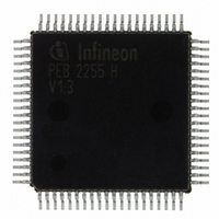
PEB2255H-V13 Infineon Technologies, PEB2255H-V13 Datasheet - Page 53

PEB2255H-V13
Manufacturer Part Number
PEB2255H-V13
Description
IC INTERFACE LINE 80-MQFP
Manufacturer
Infineon Technologies
Datasheet
1.PEB2255H-V13.pdf
(374 pages)
Specifications of PEB2255H-V13
Applications
*
Interface
*
Voltage - Supply
*
Package / Case
80-SQFP
Mounting Type
Surface Mount
Lead Free Status / RoHS Status
Lead free / RoHS Compliant
Other names
PEB2255H-V13
PEB2255H-V13IN
PEB2255H-V13IN
Available stocks
Company
Part Number
Manufacturer
Quantity
Price
Company:
Part Number:
PEB2255H-V13
Manufacturer:
Infineon Technologies
Quantity:
10 000
- Current page: 53 of 374
- Download datasheet (6Mb)
Figure 10
Test handling is performed via the pins TCK (Test Clock), TMS (Test Mode Select), TDI
(Test Data Input) and TDO (Test Data Output). Test data at TDI are loaded with a 4-MHz
clock signal connected to TCK. ‘1’ or ‘0’ on TMS causes a transition from one controller
state to an other; constant ’1’ on TMS leads to normal operation of the chip.
If no boundary scan testing is planned TMS and TDI do not need to be connected since
pull-up transistors ensure high input levels in this case. After switching on the device
(power-on), a reset signal is generated internally, which forces the TAP controller into
test logic reset state.
Data Sheet
TMS
TDO
TCK
TDI
CLOCK
Test
Control
Data IN
Enable
Data OUT
Block Diagram of Test Access Port and Boundary Scan
Test Access Port
Generation
Clock
-Finite State Machine
-Instruction Register (3 bits)
-Test Signal Generator
CLOCK
TAP Controller
53
Power ON
Reset
Reset
Functional Description E1/T1/J1
BS Data IN
Control Bus
ID Data OUT
SS Data OUT
6
FALC-LH V1.3
PEB 2255
2000-07
1
2
n
ITB09842
Pins
Related parts for PEB2255H-V13
Image
Part Number
Description
Manufacturer
Datasheet
Request
R

Part Number:
Description:
E1/t1/j1 Framer And Line Interface Component For Long And Short Haul Applications
Manufacturer:
Infineon Technologies Corporation
Datasheet:

Part Number:
Description:
Manufacturer:
Infineon Technologies AG
Datasheet:

Part Number:
Description:
Manufacturer:
Infineon Technologies AG
Datasheet:

Part Number:
Description:
Manufacturer:
Infineon Technologies AG
Datasheet:

Part Number:
Description:
Manufacturer:
Infineon Technologies AG
Datasheet:

Part Number:
Description:
Manufacturer:
Infineon Technologies AG
Datasheet:

Part Number:
Description:
Manufacturer:
Infineon Technologies AG
Datasheet:

Part Number:
Description:
Manufacturer:
Infineon Technologies AG
Datasheet:

Part Number:
Description:
16-bit microcontroller with 2x2 KByte RAM
Manufacturer:
Infineon Technologies AG
Datasheet:

Part Number:
Description:
NPN silicon RF transistor
Manufacturer:
Infineon Technologies AG
Datasheet:

Part Number:
Description:
NPN silicon RF transistor
Manufacturer:
Infineon Technologies AG
Datasheet:

Part Number:
Description:
NPN silicon RF transistor
Manufacturer:
Infineon Technologies AG
Datasheet:

Part Number:
Description:
NPN silicon RF transistor
Manufacturer:
Infineon Technologies AG
Datasheet:

Part Number:
Description:
Si-MMIC-amplifier in SIEGET 25-technologie
Manufacturer:
Infineon Technologies AG
Datasheet:

Part Number:
Description:
IGBT Power Module
Manufacturer:
Infineon Technologies AG
Datasheet:


