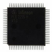
PEB2255H-V13 Infineon Technologies, PEB2255H-V13 Datasheet - Page 85

PEB2255H-V13
Manufacturer Part Number
PEB2255H-V13
Description
IC INTERFACE LINE 80-MQFP
Manufacturer
Infineon Technologies
Datasheet
1.PEB2255H-V13.pdf
(374 pages)
Specifications of PEB2255H-V13
Applications
*
Interface
*
Voltage - Supply
*
Package / Case
80-SQFP
Mounting Type
Surface Mount
Lead Free Status / RoHS Status
Lead free / RoHS Compliant
Other names
PEB2255H-V13
PEB2255H-V13IN
PEB2255H-V13IN
Available stocks
Company
Part Number
Manufacturer
Quantity
Price
Company:
Part Number:
PEB2255H-V13
Manufacturer:
Infineon Technologies
Quantity:
10 000
- Current page: 85 of 374
- Download datasheet (6Mb)
The resynchronization procedure starts automatically after reaching the asynchronous
state. Additionally, it may be invoked user controlled via bit: FMR0.FRS (Force
Resynchronization: the FAS word detection is interrupted until the framer is in the
asynchronous state. After that, resynchronization starts automatically).
Synchronous state is established after detecting:
• a correct FAS word in frame n,
• the presence of the correct service word (bit 2 = 1) in frame n + 1,
• a correct FAS word in frame n + 2.
If the service word in frame n + 1 or the FAS word in frame n + 2 or both are not found
searching for the next FAS word starts in frame n + 2 just after the previous frame
alignment signal.
Reaching the synchronous state causes a frame alignment recovery interrupt status
ISR2.FAR if enabled. Undisturbed operation starts with the beginning of the next
doubleframe.
4.4.2.3
If the FALC
interrupt status bit ISR2.RA is set. With setting of bit XSW.XRA a remote alarm (RAI) is
send to the far end.
By setting FMR2.AXRA the FALC
the outgoing data stream if the receiver detects a loss of frame alignment FRS0.LFA = 1.
If the receiver is in synchronous state FRS0.LFA = 0 the remote alarm bit is reset.
Note: The A-bit may be processed via the system interface. Setting bit TSWM.TRA
4.4.2.4
As an extension for access to the S
implemented to allow the usage of internal S
doubleframe format.
This function is enabled by setting FMR1.ENSA = 1 for the transmitter and FMR1.RFS1/
0 = 01 for the receiver. The FALC
but no CRC multiframe alignment/generation is performed.
Data Sheet
enables transparency for the A bit in transmit direction (refer to
A-Bit Access
S
®
a
-LH detects a remote alarm indication in the received data stream the
- Bit Access
®
®
-LH automatically transmit the remote alarm bit = 1 in
-LH works then internally with a 16-frame structure
a
-bits via registers RSA4-8/XSA4-8 an option is
85
a
-bit registers RSA4-8/XSA4-8 in
Functional Description E1
Table Table
FALC-LH V1.3
PEB 2255
2000-07
18).
Related parts for PEB2255H-V13
Image
Part Number
Description
Manufacturer
Datasheet
Request
R

Part Number:
Description:
E1/t1/j1 Framer And Line Interface Component For Long And Short Haul Applications
Manufacturer:
Infineon Technologies Corporation
Datasheet:

Part Number:
Description:
Manufacturer:
Infineon Technologies AG
Datasheet:

Part Number:
Description:
Manufacturer:
Infineon Technologies AG
Datasheet:

Part Number:
Description:
Manufacturer:
Infineon Technologies AG
Datasheet:

Part Number:
Description:
Manufacturer:
Infineon Technologies AG
Datasheet:

Part Number:
Description:
Manufacturer:
Infineon Technologies AG
Datasheet:

Part Number:
Description:
Manufacturer:
Infineon Technologies AG
Datasheet:

Part Number:
Description:
Manufacturer:
Infineon Technologies AG
Datasheet:

Part Number:
Description:
16-bit microcontroller with 2x2 KByte RAM
Manufacturer:
Infineon Technologies AG
Datasheet:

Part Number:
Description:
NPN silicon RF transistor
Manufacturer:
Infineon Technologies AG
Datasheet:

Part Number:
Description:
NPN silicon RF transistor
Manufacturer:
Infineon Technologies AG
Datasheet:

Part Number:
Description:
NPN silicon RF transistor
Manufacturer:
Infineon Technologies AG
Datasheet:

Part Number:
Description:
NPN silicon RF transistor
Manufacturer:
Infineon Technologies AG
Datasheet:

Part Number:
Description:
Si-MMIC-amplifier in SIEGET 25-technologie
Manufacturer:
Infineon Technologies AG
Datasheet:

Part Number:
Description:
IGBT Power Module
Manufacturer:
Infineon Technologies AG
Datasheet:


