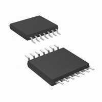
AT89LP214-20XU Atmel, AT89LP214-20XU Datasheet - Page 24

AT89LP214-20XU
Manufacturer Part Number
AT89LP214-20XU
Description
MCU 8051 2K FLASH 20MHZ 14-TSSOP
Manufacturer
Atmel
Series
89LPr
Datasheet
1.AT89LP213-20PU.pdf
(98 pages)
Specifications of AT89LP214-20XU
Core Processor
8051
Core Size
8-Bit
Speed
20MHz
Connectivity
SPI, UART/USART
Peripherals
Brown-out Detect/Reset, POR, PWM, WDT
Number Of I /o
12
Program Memory Size
2KB (2K x 8)
Program Memory Type
FLASH
Ram Size
128 x 8
Voltage - Supply (vcc/vdd)
2.4 V ~ 5.5 V
Oscillator Type
Internal
Operating Temperature
-40°C ~ 85°C
Package / Case
14-TSSOP
Package
14TSSOP
Device Core
8051
Family Name
AT89
Maximum Speed
20 MHz
Operating Supply Voltage
2.5|3.3|5 V
Data Bus Width
8 Bit
Number Of Programmable I/os
12
Interface Type
SPI/UART
Number Of Timers
2
Core
8051
Processor Series
AT89x
Maximum Clock Frequency
20 MHz
Data Ram Size
128 B
Mounting Style
SMD/SMT
Height
1.05 mm
Length
5.1 mm
Maximum Operating Temperature
+ 85 C
Minimum Operating Temperature
- 40 C
Supply Voltage (max)
5.5 V
Supply Voltage (min)
2.4 V
Width
4.5 mm
Lead Free Status / RoHS Status
Lead free / RoHS Compliant
Eeprom Size
-
Data Converters
-
Lead Free Status / Rohs Status
Details
13.1
13.1.1
24
Port Configuration
AT89LP213/214
Quasi-bidirectional Output
All port pins on the AT89LP213/214 may be configured to one of four modes: quasi-bidirectional
(standard 8051 port outputs), push-pull output, open-drain output, or input-only. Port modes may
be assigned in software on a pin-by-pin basis as shown in
Fuse determines the default state of the port pins. When the fuse is enabled, all port pins default
to input-only mode after reset, with the exception of P1.4 which starts in quasi-bidirectional
mode. When the fuse is disabled, all port pins, with the exception of P1.0 and P1.1, default to
quasi-bidirectional mode after reset and are weakly pulled high. Each port pin also has a
Schmitt-triggered input for improved input noise rejection. During Power-down all the Schmitt-
triggered inputs are disabled with the exception of P1.3, P3.2 and P3.3, which may be used to
wake up the device. Therefore P1.3, P3.2 and P3.3 should not be left floating during Power-
down. It is recommended that P3.1–0 on AT89LP213 and P3.4–5 on AT89LP214 be configured
for either quasi-bidirectional or push-pull output mode.
.
Table 13-2.
Port pins in quasi-bidirectional output mode function similar to standard 8051 port pins. A Quasi-
bidirectional port can be used both as an input and output without the need to reconfigure the
port. This is possible because when the port outputs a logic high, it is weakly driven, allowing an
external device to pull the pin low. When the pin is driven low, it is driven strongly and able to
sink a large current. There are three pull-up transistors in the quasi-bidirectional output that
serve different purposes. One of these pull-ups, called the “very weak” pull-up, is turned on
whenever the port latch for the pin contains a logic “1”. This very weak pull-up sources a very
small current that will pull the pin high if it is left floating.
A second pull-up, called the “weak” pull-up, is turned on when the port latch for the pin contains
a logic “1” and the pin itself is also at a logic “1” level. This pull-up provides the primary source
current for a quasi-bidirectional pin that is outputting a “1”. If this pin is pulled low by an external
device, this weak pull-up turns off, and only the very weak pull-up remains on. In order to pull the
pin low under these conditions, the external device has to sink enough current to overpower the
weak pull-up and pull the port pin below its input threshold voltage.
The third pull-up is referred to as the “strong” pull-up. This pull-up is used to speed up low-to-
high transitions on a quasi-bidirectional port pin when the port latch changes from a logic “0” to a
logic “1”. When this occurs, the strong pull-up turns on for two CPU clocks quickly pulling the
port pin high. The quasi-bidirectional port configuration is shown in
cuitry of P1.3, P3.2 and P3.3 is not disabled during Power-down (see
PxM0.y
0
0
1
1
Configuration Modes for Port x, Bit y
PxM1.y
0
1
0
1
Port Mode
Quasi-bidirectional
Push-pull Output
Input Only (High Impedance)
Open-drain Output
Table
13-2. The Tristate-Port User
Figure
Figure
13-1. The input cir-
13-3).
3538E–MICRO–11/10


