P80C592FFA/00,512 NXP Semiconductors, P80C592FFA/00,512 Datasheet - Page 51
P80C592FFA/00,512
Manufacturer Part Number
P80C592FFA/00,512
Description
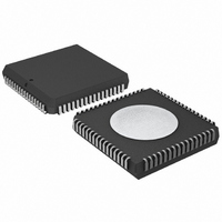
IC 80C51 MCU 8BIT ROMLESS 68PLCC
Manufacturer
NXP Semiconductors
Series
80Cr
Datasheet
1.P80C592FFA00512.pdf
(108 pages)
Specifications of P80C592FFA/00,512
Program Memory Type
ROMless
Package / Case
68-PLCC
Core Processor
8051
Core Size
8-Bit
Speed
16MHz
Connectivity
CAN, EBI/EMI, UART/USART
Peripherals
DMA, POR, PWM, WDT
Number Of I /o
48
Ram Size
512 x 8
Voltage - Supply (vcc/vdd)
4.5 V ~ 5.5 V
Data Converters
A/D 8x10b
Oscillator Type
Internal
Operating Temperature
-40°C ~ 85°C
Processor Series
P80C5x
Core
80C51
Data Bus Width
8 bit
Data Ram Size
512 B
Interface Type
CAN/UART
Maximum Clock Frequency
16 MHz
Number Of Programmable I/os
40
Number Of Timers
3
Maximum Operating Temperature
+ 85 C
Mounting Style
SMD/SMT
3rd Party Development Tools
PK51, CA51, A51, ULINK2
Minimum Operating Temperature
- 40 C
On-chip Adc
8-ch x 10-bit
Cpu Family
80C
Device Core
80C51
Device Core Size
8b
Frequency (max)
16MHz
Program Memory Size
Not Required
Total Internal Ram Size
512Byte
# I/os (max)
40
Number Of Timers - General Purpose
3
Operating Supply Voltage (typ)
5V
Operating Supply Voltage (max)
5.5V
Operating Supply Voltage (min)
4.5V
Instruction Set Architecture
CISC
Operating Temp Range
-40C to 85C
Operating Temperature Classification
Industrial
Mounting
Surface Mount
Pin Count
68
Package Type
PLCC
Lead Free Status / RoHS Status
Lead free / RoHS Compliant
Eeprom Size
-
Program Memory Size
-
Lead Free Status / Rohs Status
Compliant
Other names
568-1241-5
935086530512
P80C592FFAA
935086530512
P80C592FFAA
Available stocks
Company
Part Number
Manufacturer
Quantity
Price
Company:

Part Number:
P80C592FFA/00,512
Manufacturer:
ON
Quantity:
300
Company:
Part Number:
P80C592FFA/00,512
Manufacturer:
NXP Semiconductors
Quantity:
10 000


Philips Semiconductors
13.5.16 A
With the Auto Address Increment mode a fast stack-like
reading and writing of CAN-controller internal registers is
provided. If the bit CANADR.5 (AutoInc) is HIGH, the
content of CANADR is incremented automatically after any
read or write access to CANDAT. For instance, loading a
message into the Transmit Buffer can be done by writing
2AH into CANADR and then moving byte by byte of the
message to CANDAT. Incrementing CANADR beyond
XX111111B resets the bit CANADR.5 (AutoInc)
automatically (CANADR = XX000000B).
13.5.17 H
The DMA-logic allows you to transfer a complete message
(up to 10 bytes) between CAN-controller and MAIN RAM
in 2 instruction cycles at maximum; up to 4 bytes are
transferred in 1 instruction cycle. The performance of the
CPU is strongly enhanced because this very fast transfer
is carried out in the background.
A DMA transfer is achieved by first writing the RAM
address (00H to FFH) into CANSTA and then setting the
TX- or RX-Buffer address in CANDR and the bit
CANADR.7 (DMA) simultaneously; the RAM address
points to the location of the first byte to be transferred.
Setting the DMA bit causes an automatic evaluation of the
Data Length Code and then the transfer; for a TX-DMA
transfer the Data Length Code is expected at the location
‘RAM address +1’.
In order to program a TX-DMA transfer the value 8AH
(address 10) has to be written into CANADR. Then a
complete message, consisting of the 2-byte Descriptor
and the Data Field (0 to 8 bytes), starting at location
‘RAM address’ is transferred to the TX-Buffer.
The RX-DMA transfer is very versatile. By writing a value
in the range of 94H (address 20) up to 9DH (address 29)
into CANADR the whole or a part of the received message,
starting at the specified address, is transferred to the
internal Data Memory. This allows e.g. to transfer the bytes
of the Data Field only.
After a successful DMA transfer the DMA-bit is reset.
During a DMA transfer the CPU can process the next
instruction. However, an access to the Data Memory,
1996 Jun 27
8-bit microcontroller with on-chip CAN
UTO ADDRESS INCREMENT
IGH SPEED
DMA
51
CANADR, CANDAT, CANCON or CANSTA is not allowed.
After having set the DMA-bit, every interrupt is disabled
until the end of the transfer. Note, that disadvantageous
programming may lead to an interrupt response time of at
most 10 instruction cycles. The shortest interrupt response
time is achieved by using 2 consecutive 1-cycle
instructions directly after setting the DMA-bit.
During the reset state (bit Reset Request is HIGH) a DMA
transfer is not possible.
13.5.18 B
The Bus Timing Logic (BTL) monitors the serial bus-line
via the on-chip input comparator and performs the
following functions (see Section 13.4):
The configuration of the BTL is performed during the
initialization of the CAN-controller. The BTL uses the
following three registers:
13.5.19 B
A bit period is built up from a number of system clock
cycles (t
One bit period is the result of the addition of the
programmable segments TSEG1 and TSEG2 and the
general segment SYNCSEG.
13.5.19.1 Synchronization Segment (SYNCSEG)
The incoming edge of a bit is expected during this state;
this state corresponds to one system clock cycle (1
Monitors the serial bus-line level
Adjusts the sample point, within a bit period
(programmable)
Samples the bus-line level using majority logic
(programmable, 1 or 3 samples)
Synchronization to the bit stream:
– hard synchronization at the start of a message
– resynchronization during transfer of a message.
Control Register (Sync)
Bus Timing Register 0
Bus Timing Register 1.
SCL
US TIMING
IT TIMING
), see Section 13.5.9.
/
SYNCHRONIZATION
Product specification
P8xC592
t
SCL
).
Related parts for P80C592FFA/00,512
Image
Part Number
Description
Manufacturer
Datasheet
Request
R

Part Number:
Description:
Manufacturer:
NXP Semiconductors
Datasheet:

Part Number:
Description:
IC 80C51 MCU 8BIT ROMLESS 68PLCC
Manufacturer:
NXP Semiconductors
Datasheet:
Part Number:
Description:
8-bit Microcontroller With On-chip Can
Manufacturer:
NXP Semiconductors
Datasheet:

Part Number:
Description:
8-bit microcontroller with on-chip CAN
Manufacturer:
Philips Semiconductors
Datasheet:
Part Number:
Description:
NXP Semiconductors designed the LPC2420/2460 microcontroller around a 16-bit/32-bitARM7TDMI-S CPU core with real-time debug interfaces that include both JTAG andembedded trace
Manufacturer:
NXP Semiconductors
Datasheet:

Part Number:
Description:
NXP Semiconductors designed the LPC2458 microcontroller around a 16-bit/32-bitARM7TDMI-S CPU core with real-time debug interfaces that include both JTAG andembedded trace
Manufacturer:
NXP Semiconductors
Datasheet:
Part Number:
Description:
NXP Semiconductors designed the LPC2468 microcontroller around a 16-bit/32-bitARM7TDMI-S CPU core with real-time debug interfaces that include both JTAG andembedded trace
Manufacturer:
NXP Semiconductors
Datasheet:
Part Number:
Description:
NXP Semiconductors designed the LPC2470 microcontroller, powered by theARM7TDMI-S core, to be a highly integrated microcontroller for a wide range ofapplications that require advanced communications and high quality graphic displays
Manufacturer:
NXP Semiconductors
Datasheet:
Part Number:
Description:
NXP Semiconductors designed the LPC2478 microcontroller, powered by theARM7TDMI-S core, to be a highly integrated microcontroller for a wide range ofapplications that require advanced communications and high quality graphic displays
Manufacturer:
NXP Semiconductors
Datasheet:
Part Number:
Description:
The Philips Semiconductors XA (eXtended Architecture) family of 16-bit single-chip microcontrollers is powerful enough to easily handle the requirements of high performance embedded applications, yet inexpensive enough to compete in the market for hi
Manufacturer:
NXP Semiconductors
Datasheet:
Part Number:
Description:
The XA-S3 device is a member of Philips Semiconductors? XA(eXtended Architecture) family of high performance 16-bitsingle-chip microcontrollers
Manufacturer:
NXP Semiconductors
Datasheet:

Part Number:
Description:
The NXP BlueStreak LH75401/LH75411 family consists of two low-cost 16/32-bit System-on-Chip (SoC) devices
Manufacturer:
NXP Semiconductors
Datasheet:
Part Number:
Description:
The NXP LPC3130/3131 combine an 180 MHz ARM926EJ-S CPU core, high-speed USB2
Manufacturer:
NXP Semiconductors
Datasheet:
Part Number:
Description:
The NXP LPC3141 combine a 270 MHz ARM926EJ-S CPU core, High-speed USB 2
Manufacturer:
NXP Semiconductors