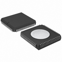
P80C592FFA/00,512 NXP Semiconductors, P80C592FFA/00,512 Datasheet - Page 67

P80C592FFA/00,512
Manufacturer Part Number
P80C592FFA/00,512
Description
IC 80C51 MCU 8BIT ROMLESS 68PLCC
Manufacturer
NXP Semiconductors
Series
80Cr
Datasheet
1.P80C592FFA00512.pdf
(108 pages)
Specifications of P80C592FFA/00,512
Program Memory Type
ROMless
Package / Case
68-PLCC
Core Processor
8051
Core Size
8-Bit
Speed
16MHz
Connectivity
CAN, EBI/EMI, UART/USART
Peripherals
DMA, POR, PWM, WDT
Number Of I /o
48
Ram Size
512 x 8
Voltage - Supply (vcc/vdd)
4.5 V ~ 5.5 V
Data Converters
A/D 8x10b
Oscillator Type
Internal
Operating Temperature
-40°C ~ 85°C
Processor Series
P80C5x
Core
80C51
Data Bus Width
8 bit
Data Ram Size
512 B
Interface Type
CAN/UART
Maximum Clock Frequency
16 MHz
Number Of Programmable I/os
40
Number Of Timers
3
Maximum Operating Temperature
+ 85 C
Mounting Style
SMD/SMT
3rd Party Development Tools
PK51, CA51, A51, ULINK2
Minimum Operating Temperature
- 40 C
On-chip Adc
8-ch x 10-bit
Cpu Family
80C
Device Core
80C51
Device Core Size
8b
Frequency (max)
16MHz
Program Memory Size
Not Required
Total Internal Ram Size
512Byte
# I/os (max)
40
Number Of Timers - General Purpose
3
Operating Supply Voltage (typ)
5V
Operating Supply Voltage (max)
5.5V
Operating Supply Voltage (min)
4.5V
Instruction Set Architecture
CISC
Operating Temp Range
-40C to 85C
Operating Temperature Classification
Industrial
Mounting
Surface Mount
Pin Count
68
Package Type
PLCC
Lead Free Status / RoHS Status
Lead free / RoHS Compliant
Eeprom Size
-
Program Memory Size
-
Lead Free Status / Rohs Status
Compliant
Other names
568-1241-5
935086530512
P80C592FFAA
935086530512
P80C592FFAA
Available stocks
Company
Part Number
Manufacturer
Quantity
Price
Company:
Part Number:
P80C592FFA/00,512
Manufacturer:
ON
Quantity:
300
Company:
Part Number:
P80C592FFA/00,512
Manufacturer:
NXP Semiconductors
Quantity:
10 000
Philips Semiconductors
14.2
The vector indicates the Program Memory location where
the appropriate interrupt service routine starts
(see Table 79).
Table 79 Interrupt vectors
1996 Jun 27
External 0
Timer 0 overflow
External 1
Timer 1 overflow
Serial I/O 0 (UART)
Serial I/O 1 (CAN)
T2 capture 0
T2 capture 1
T2 capture 2
T2 capture 3
ADC completion
T2 compare 0
T2 compare 1
T2 compare 2
T2 overflow
handbook, full pagewidth
8-bit microcontroller with on-chip CAN
Interrupt Vectors
SOURCE
XTAL2
Fig.22 Internal Sleep, Idle and Power-down clock configuration.
X0
T0
X1
T1
S0
S1
CT0
CT1
CT2
CT3
ADC
CM0
CM1
CM2
T2
OSCILLATOR
BIT
VECTOR
000BH
001BH
002BH
003BH
004BH
005BH
006BH
0003H
0013H
0023H
0033H
0043H
0053H
0063H
0073H
PD
XTAL1
sleep
67
14.3
Each interrupt source can be either high priority or low
priority. If both priorities are requested simultaneously, the
processor will branch to the high priority vector. If there are
simultaneous requests from sources of the same priority,
then interrupts will be serviced in the following order:
X0, S1, ADC, T0, CT0, CM0, X1, CT1, CM1, T1, CT2,
CM2, S0, CT3, T2.
A low priority interrupt routine can only be interrupted by a
high priority interrupt. A high priority interrupt routine can
not be interrupted.
15 POWER REDUCTION MODES
The P8xC592 has three software-selectable modes to
reduce power consumption. These are:
Sleep mode, affecting the CAN-controller only
Idle mode, affecting the
– CPU (halted)
– Timer 2 (stopped and reset)
– PWM0, PWM1 (reset, output = HIGH)
– ADC (aborted if in progress)
Power-down mode, affecting the whole P8xC592
device.
GENERATOR
CLOCK
Interrupt Priority
IDL
interrupts
serial ports
timer blocks
CPU
CAN
PWM
ADC
T2
MGA167
Product specification
P8xC592


