DF2265TE13V Renesas Electronics America, DF2265TE13V Datasheet - Page 337
DF2265TE13V
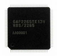
Manufacturer Part Number
DF2265TE13V
Description
IC H8S/2265 MCU FLASH 100TQFP
Manufacturer
Renesas Electronics America
Series
H8® H8S/2200r
Specifications of DF2265TE13V
Core Processor
H8S/2000
Core Size
16-Bit
Speed
13MHz
Connectivity
I²C, SCI, SmartCard
Peripherals
LCD, POR, PWM, WDT
Number Of I /o
67
Program Memory Size
128KB (128K x 8)
Program Memory Type
FLASH
Ram Size
4K x 8
Voltage - Supply (vcc/vdd)
3 V ~ 5.5 V
Data Converters
A/D 10x10b, D/A 2x8b
Oscillator Type
Internal
Operating Temperature
-20°C ~ 75°C
Package / Case
100-TQFP, 100-VQFP
Lead Free Status / RoHS Status
Lead free / RoHS Compliant
Eeprom Size
-
Available stocks
Company
Part Number
Manufacturer
Quantity
Price
Company:

Part Number:
DF2265TE13V
Manufacturer:
Renesas Electronics America
Quantity:
10 000


11.11.2 Automatic Reload Timer Operation
When the ARSL bit in TCR is set to 1, the timer operates as an automatic reload timer.
When a reload value is set to TLR, the value is also loaded to TCNT simultaneously, and TCNT
starts incrementation from the value.
If a clock is input after the TCNT count value reaches H'FF, the timer overflows, the TLR value is
written to TCNT, and incrementation is continued from the value. Therefore, the overflow cycle
can be set within the range from 1 to 256, using a TLR value.
Clock sources and interrupts in automatic reload operation are the same as those in interval
operation. If TLR is re-set during automatic reload operation, the value is also set to TCNT.
This operation timing is shown in figure 11.15.
11.11.3 Cascaded Connection
• Read of TCNT
H'FF
H'80
H'40
H'00
TCNT value
The channel relationship for cascaded connection is shown in figure 11.16.
When accessing beyond the word area, for example, when a cascaded connection including
channels 5 and 6 is created as shown in (3), and (6) to (8) in the figure, the counter value of the
lower channel is read when TCNT5 is read, and the data is stored in the TCNT register.
For case (7) where channels 5 to 7 are cascaded, the counter values of channels 6 and 7 are
read when TCNT5 is read, and the data is stored in TCNT6/7 registers. Accordingly, when
reading cascaded TCNT, read from the upper channel.
MSTPD5 = 0
ARSL = 0
Figure 11.15 Operation in Automatic Reload Timer Mode
ARSL = 1
TLR setting
(H'80))
Overflow
OVF
Overflow
OVF
Overflow
OVF
Rev. 5.00 Sep. 01, 2009 Page 285 of 656
Overflow
OVF
OVF: Timer overflow interrupt request generation
TLR setting
(H'40)
Overflow
Section 11 8-Bit Timers
OVF
REJ09B0071-0500
Overflow
OVF
Time
Related parts for DF2265TE13V
Image
Part Number
Description
Manufacturer
Datasheet
Request
R

Part Number:
Description:
CONN SOCKET 2POS 7.92MM WHITE
Manufacturer:
Hirose Electric Co Ltd
Datasheet:

Part Number:
Description:
CONN SOCKET 4POS 7.92MM WHITE
Manufacturer:
Hirose Electric Co Ltd
Datasheet:

Part Number:
Description:
CONN SOCKET 5POS 7.92MM WHITE
Manufacturer:
Hirose Electric Co Ltd
Datasheet:

Part Number:
Description:
CONN SOCKET 3POS 7.92MM WHITE
Manufacturer:
Hirose Electric Co Ltd
Datasheet:
Part Number:
Description:
CONN SOCKET 5POS 7.92MM WHITE
Manufacturer:
Hirose Electric Co Ltd
Datasheet:

Part Number:
Description:
CONN SOCKET 2POS 7.92MM WHITE
Manufacturer:
Hirose Electric Co Ltd
Datasheet:
Part Number:
Description:
CONN SOCKET 3POS 7.92MM WHITE
Manufacturer:
Hirose Electric Co Ltd
Datasheet:
Part Number:
Description:
CONN SOCKET 4POS 7.92MM WHITE
Manufacturer:
Hirose Electric Co Ltd
Datasheet:

Part Number:
Description:
CONN HEADER 2POS 7.92MM R/A TIN
Manufacturer:
Hirose Electric Co Ltd
Datasheet:

Part Number:
Description:
CONN HEADER 4POS 7.92MM R/A TIN
Manufacturer:
Hirose Electric Co Ltd
Datasheet:

Part Number:
Description:
KIT STARTER FOR M16C/29
Manufacturer:
Renesas Electronics America
Datasheet:

Part Number:
Description:
KIT STARTER FOR R8C/2D
Manufacturer:
Renesas Electronics America
Datasheet:

Part Number:
Description:
R0K33062P STARTER KIT
Manufacturer:
Renesas Electronics America
Datasheet:

Part Number:
Description:
KIT STARTER FOR R8C/23 E8A
Manufacturer:
Renesas Electronics America
Datasheet:

Part Number:
Description:
KIT STARTER FOR R8C/25
Manufacturer:
Renesas Electronics America
Datasheet: