DF2265TE13V Renesas Electronics America, DF2265TE13V Datasheet - Page 468
DF2265TE13V
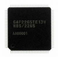
Manufacturer Part Number
DF2265TE13V
Description
IC H8S/2265 MCU FLASH 100TQFP
Manufacturer
Renesas Electronics America
Series
H8® H8S/2200r
Specifications of DF2265TE13V
Core Processor
H8S/2000
Core Size
16-Bit
Speed
13MHz
Connectivity
I²C, SCI, SmartCard
Peripherals
LCD, POR, PWM, WDT
Number Of I /o
67
Program Memory Size
128KB (128K x 8)
Program Memory Type
FLASH
Ram Size
4K x 8
Voltage - Supply (vcc/vdd)
3 V ~ 5.5 V
Data Converters
A/D 10x10b, D/A 2x8b
Oscillator Type
Internal
Operating Temperature
-20°C ~ 75°C
Package / Case
100-TQFP, 100-VQFP
Lead Free Status / RoHS Status
Lead free / RoHS Compliant
Eeprom Size
-
Available stocks
Company
Part Number
Manufacturer
Quantity
Price
Company:

Part Number:
DF2265TE13V
Manufacturer:
Renesas Electronics America
Quantity:
10 000


Section 14 I
[12] The IRIC flag is set to 1 by the following two conditions.
[13] Read the IRTR flag in ICSR. If the IRTR flag value is 0, the wait state is cancelled by
[14] If the IRTR flag value is 0, clear the IRIC flag to 0 to cancel the wait state. Return to reading
[15] Clear the WAIT bit in ICMR to 0 to cancel the wait mode. Then clear the IRIC flag to 0. The
[16] Read the final receive data in ICDR.
[17] Write 0 to BBSY and SCP in ICCR. This changes SDA from low to high when SCL is high,
Rev. 5.00 Sep. 01, 2009 Page 416 of 656
REJ09B0071-0500
SCL
(master output)
SDA
(slave output)
SDA
(master output)
IRIC
IRTR
ICDR
User processing
Master transmit mode
(1) The flag is set at the falling edge of the 8th clock cycle of the receive clock for 1 frame.
(2) The flag is set at the rising edge of the 9th clock cycle of the receive clock for 1 frame.
clearing the IRIC flag as described in step [14] below. If the IRTR flag value is 1 and the
receive operation has finished, perform the issue stop condition processing described in step
[15] below.
the IRIC flag, as described in step [12], to detect the end of the receive operation.
IRIC flag should be cleared when the value of WAIT is 0. (The stop condition may not be
output properly when the issue stop condition instruction is executed if the WAIT bit was
cleared to 0 after the IRIC flag is cleared to 0.)
and generates the stop condition.
SCL is automatically held low, in synchronization with the internal clock, until the IRIC
flag is cleared.
The IRTR flag is set to 1, indicating that reception of 1 frame of data has ended. The
master device continues to output the receive clock for the receive data.
2
C Bus Interface (IIC) (Supported as an Option by H8S/2264 Group)
Figure 14.12 Example of Master Receive Mode Operation Timing
A
9
[1] TRS cleared to 0
IRIC clearance
Bit 7 Bit 6 Bit 5 Bit 4 Bit 3
[2] ICDR read (dummy read)
Master receive mode
1
2
(MLS = ACKB = 0, WAIT = 1)
3
Data 1
4
5
Bit 2 Bit 1 Bit 0
6
7
[6] IRIC clearance
8
(cancel wait)
[4] IRTR = 0
[3]
A
[3]
[4] IRTR = 1
9
[5] ICDR read
(data 1)
Bit 7 Bit 6 Bit 5 Bit 4 Bit 3
Data 1
1
2
Data 2
[6] IRIC clearance
3
4
5
Related parts for DF2265TE13V
Image
Part Number
Description
Manufacturer
Datasheet
Request
R

Part Number:
Description:
CONN SOCKET 2POS 7.92MM WHITE
Manufacturer:
Hirose Electric Co Ltd
Datasheet:

Part Number:
Description:
CONN SOCKET 4POS 7.92MM WHITE
Manufacturer:
Hirose Electric Co Ltd
Datasheet:

Part Number:
Description:
CONN SOCKET 5POS 7.92MM WHITE
Manufacturer:
Hirose Electric Co Ltd
Datasheet:

Part Number:
Description:
CONN SOCKET 3POS 7.92MM WHITE
Manufacturer:
Hirose Electric Co Ltd
Datasheet:
Part Number:
Description:
CONN SOCKET 5POS 7.92MM WHITE
Manufacturer:
Hirose Electric Co Ltd
Datasheet:

Part Number:
Description:
CONN SOCKET 2POS 7.92MM WHITE
Manufacturer:
Hirose Electric Co Ltd
Datasheet:
Part Number:
Description:
CONN SOCKET 3POS 7.92MM WHITE
Manufacturer:
Hirose Electric Co Ltd
Datasheet:
Part Number:
Description:
CONN SOCKET 4POS 7.92MM WHITE
Manufacturer:
Hirose Electric Co Ltd
Datasheet:

Part Number:
Description:
CONN HEADER 2POS 7.92MM R/A TIN
Manufacturer:
Hirose Electric Co Ltd
Datasheet:

Part Number:
Description:
CONN HEADER 4POS 7.92MM R/A TIN
Manufacturer:
Hirose Electric Co Ltd
Datasheet:

Part Number:
Description:
KIT STARTER FOR M16C/29
Manufacturer:
Renesas Electronics America
Datasheet:

Part Number:
Description:
KIT STARTER FOR R8C/2D
Manufacturer:
Renesas Electronics America
Datasheet:

Part Number:
Description:
R0K33062P STARTER KIT
Manufacturer:
Renesas Electronics America
Datasheet:

Part Number:
Description:
KIT STARTER FOR R8C/23 E8A
Manufacturer:
Renesas Electronics America
Datasheet:

Part Number:
Description:
KIT STARTER FOR R8C/25
Manufacturer:
Renesas Electronics America
Datasheet: