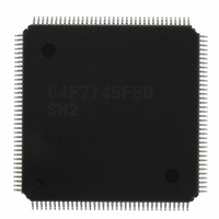
HD64F7145F50 Renesas Electronics America, HD64F7145F50 Datasheet - Page 134

HD64F7145F50
Manufacturer Part Number
HD64F7145F50
Description
IC SUPERH MCU FLASH 256K FP144F
Manufacturer
Renesas Electronics America
Series
SuperH® SH7144r
Datasheet
1.HD64F7144F50V.pdf
(932 pages)
Specifications of HD64F7145F50
Core Processor
SH-2
Core Size
32-Bit
Speed
50MHz
Connectivity
EBI/EMI, I²C, SCI
Peripherals
DMA, POR, PWM, WDT
Number Of I /o
98
Program Memory Size
256KB (256K x 8)
Program Memory Type
FLASH
Ram Size
8K x 8
Voltage - Supply (vcc/vdd)
3 V ~ 3.6 V
Data Converters
A/D 8x10b
Oscillator Type
Internal
Operating Temperature
-20°C ~ 75°C
Package / Case
144-LQFP
Lead Free Status / RoHS Status
Contains lead / RoHS non-compliant
Eeprom Size
-
Available stocks
Company
Part Number
Manufacturer
Quantity
Price
Part Number:
HD64F7145F50
Manufacturer:
RENESAS/瑞萨
Quantity:
20 000
Company:
Part Number:
HD64F7145F50V
Manufacturer:
Renesas Electronics America
Quantity:
10 000
Part Number:
HD64F7145F50V
Manufacturer:
RENESAS/瑞萨
Quantity:
20 000
- Current page: 134 of 932
- Download datasheet (6Mb)
6. Interrupt Controller (INTC)
6.4.2
On-chip peripheral module interrupts are interrupts generated by the following on-chip peripheral
modules.
As a different interrupt vector is assigned to each interrupt source, the exception service routine
does not have to decide which interrupt has occurred. Priority levels between 0 and 15 can be
assigned to individual on-chip peripheral modules in interrupt priority registers A to J (IPRA to
IPRJ). On-chip peripheral module interrupt exception processing sets the interrupt mask level bits
(I3 to I0) in the status register (SR) to the priority level value of the on-chip peripheral module
interrupt that was accepted.
6.4.3
A user break interrupt has a priority of level 15, and occurs when the break condition set in the
user break controller (UBC) is satisfied. User break interrupt requests are detected by edge and are
held until accepted. User break interrupt exception processing sets the interrupt mask level bits (I3
to I0) in the status register (SR) to level 15. For more details on the user break interrupt, see
section 7, User Break Controller (UBC).
Rev.4.00 Mar. 27, 2008 Page 88 of 882
REJ09B0108-0400
IRQ pins
(Acceptance of IRQn interrupt/DTC transfer end/
writing 0 after reading IRQnF = 1)
On-Chip Peripheral Module Interrupts
User Break Interrupt
Figure 6.2 Block Diagram of IRQ7 to IRQ0 Interrupts Control
detection
detection
RESIRQn
Level
Edge
S
R
Q
IRQnS
IRQnES
ISR.IRQnF
DTC starting request
DTC
CPU interrupt
request
Related parts for HD64F7145F50
Image
Part Number
Description
Manufacturer
Datasheet
Request
R

Part Number:
Description:
KIT STARTER FOR M16C/29
Manufacturer:
Renesas Electronics America
Datasheet:

Part Number:
Description:
KIT STARTER FOR R8C/2D
Manufacturer:
Renesas Electronics America
Datasheet:

Part Number:
Description:
R0K33062P STARTER KIT
Manufacturer:
Renesas Electronics America
Datasheet:

Part Number:
Description:
KIT STARTER FOR R8C/23 E8A
Manufacturer:
Renesas Electronics America
Datasheet:

Part Number:
Description:
KIT STARTER FOR R8C/25
Manufacturer:
Renesas Electronics America
Datasheet:

Part Number:
Description:
KIT STARTER H8S2456 SHARPE DSPLY
Manufacturer:
Renesas Electronics America
Datasheet:

Part Number:
Description:
KIT STARTER FOR R8C38C
Manufacturer:
Renesas Electronics America
Datasheet:

Part Number:
Description:
KIT STARTER FOR R8C35C
Manufacturer:
Renesas Electronics America
Datasheet:

Part Number:
Description:
KIT STARTER FOR R8CL3AC+LCD APPS
Manufacturer:
Renesas Electronics America
Datasheet:

Part Number:
Description:
KIT STARTER FOR RX610
Manufacturer:
Renesas Electronics America
Datasheet:

Part Number:
Description:
KIT STARTER FOR R32C/118
Manufacturer:
Renesas Electronics America
Datasheet:

Part Number:
Description:
KIT DEV RSK-R8C/26-29
Manufacturer:
Renesas Electronics America
Datasheet:

Part Number:
Description:
KIT STARTER FOR SH7124
Manufacturer:
Renesas Electronics America
Datasheet:

Part Number:
Description:
KIT STARTER FOR H8SX/1622
Manufacturer:
Renesas Electronics America
Datasheet:


