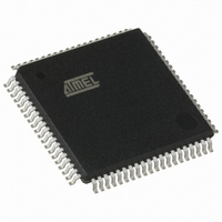
AT80C51SND1C-ROTIL Atmel, AT80C51SND1C-ROTIL Datasheet - Page 114

AT80C51SND1C-ROTIL
Manufacturer Part Number
AT80C51SND1C-ROTIL
Description
IC MCU FLASH MP3 DECODER 80-TQFP
Manufacturer
Atmel
Series
80Cr
Datasheet
1.AT80C51SND1C-ROTIL.pdf
(213 pages)
Specifications of AT80C51SND1C-ROTIL
Core Processor
8051
Core Size
8-Bit
Speed
40MHz
Connectivity
I²C, IDE/ATAPI, MMC, SPI, UART/USART, USB
Peripherals
Audio, I²S, MP3, PCM, POR, WDT
Number Of I /o
44
Program Memory Type
ROMless
Ram Size
2.25K x 8
Voltage - Supply (vcc/vdd)
2.7 V ~ 3.3 V
Data Converters
A/D 2x10b
Oscillator Type
Internal
Operating Temperature
-40°C ~ 85°C
Package / Case
80-TQFP, 80-VQFP
Lead Free Status / RoHS Status
Contains lead / RoHS non-compliant
Eeprom Size
-
Program Memory Size
-
Other names
AT80C51SND1CROTIL
Available stocks
Company
Part Number
Manufacturer
Quantity
Price
- Current page: 114 of 213
- Download datasheet (3Mb)
16.2.6
16.3
114
Description
AT8xC51SND1C
Clock Control
in stream packets, CRC protection is not included in this case. The CRC protection algorithm for
block data is a 16-bit CCITT polynomial.
Figure 16-8. Data Token Format
The MMC bus clock signal can be used by the host to turn the cards into energy saving mode or
to control the data flow (to avoid under-run or over-run conditions) on the bus. The host is
allowed to lower the clock frequency or shut it down.
There are a few restrictions the host must follow:
•
•
•
•
•
•
•
The MMC controller interfaces to the C51 core through the following eight special function
registers:
MMCON0, MMCON1, MMCON2, the three MMC control registers (see Table 113 to
MMSTA, the MMC status register (see Table 116); MMINT, the MMC interrupt register (see
Table 117); MMMSK, the MMC interrupt mask register (see Table 118); MMCMD, the MMC
command register (see Table 119); MMDAT, the MMC data register (see Table 120); and
MMCLK, the MMC clock register (see Table 121).
As shown in Figure 16-9, the MMC controller is divided in four blocks: the clock generator that
handles the MCLK (formally the MMC CLK) output to the card, the command line controller that
handles the MCMD (formally the MMC CMD) line traffic to or from the card, the data line control-
ler that handles the MDAT (formally the MMC DAT) line traffic to or from the card, and the
interrupt controller that handles the MMC controller interrupt sources. These blocks are detailed
in the following sections.
The bus frequency can be changed at any time (under the restrictions of maximum data
transfer frequency, defined by the cards, and the identification frequency defined by the
specification document).
It is an obvious requirement that the clock must be running for the card to output data or
response tokens. After the last MultiMedia Card bus transaction, the host is required, to
provide 8 (eight) clock cycles for the card to complete the operation before shutting down
the clock. Following is a list of the various bus transactions:
A command with no response. 8 clocks after the host command End bit.
A command with response. 8 clocks after the card command End bit.
A read data transaction. 8 clocks after the End bit of the last data block.
A write data transaction. 8 clocks after the CRC status token.
The host is allowed to shut down the clock of a “busy” card. The card will complete the
programming operation regardless of the host clock. However, the host must provide a clock
edge for the card to turn off its busy signal. Without a clock edge the card (unless previously
disconnected by a deselect command-CMD7) will force the MDAT line down, forever.
Sequential Data
Block Data
0
0
Block Length
Content
Content
CRC
1
1
4109L–8051–02/08
Table
121);
Related parts for AT80C51SND1C-ROTIL
Image
Part Number
Description
Manufacturer
Datasheet
Request
R

Part Number:
Description:
DEV KIT FOR AVR/AVR32
Manufacturer:
Atmel
Datasheet:

Part Number:
Description:
INTERVAL AND WIPE/WASH WIPER CONTROL IC WITH DELAY
Manufacturer:
ATMEL Corporation
Datasheet:

Part Number:
Description:
Low-Voltage Voice-Switched IC for Hands-Free Operation
Manufacturer:
ATMEL Corporation
Datasheet:

Part Number:
Description:
MONOLITHIC INTEGRATED FEATUREPHONE CIRCUIT
Manufacturer:
ATMEL Corporation
Datasheet:

Part Number:
Description:
AM-FM Receiver IC U4255BM-M
Manufacturer:
ATMEL Corporation
Datasheet:

Part Number:
Description:
Monolithic Integrated Feature Phone Circuit
Manufacturer:
ATMEL Corporation
Datasheet:

Part Number:
Description:
Multistandard Video-IF and Quasi Parallel Sound Processing
Manufacturer:
ATMEL Corporation
Datasheet:

Part Number:
Description:
High-performance EE PLD
Manufacturer:
ATMEL Corporation
Datasheet:

Part Number:
Description:
8-bit Flash Microcontroller
Manufacturer:
ATMEL Corporation
Datasheet:

Part Number:
Description:
2-Wire Serial EEPROM
Manufacturer:
ATMEL Corporation
Datasheet:


