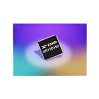
XR17D152CM-F Exar Corporation, XR17D152CM-F Datasheet - Page 39

XR17D152CM-F
Manufacturer Part Number
XR17D152CM-F
Description
IC UART PCI BUS DUAL 100TQFP
Manufacturer
Exar Corporation
Type
RS- 232 or RS- 422 or RS- 485r
Datasheet
1.XR17D152CM-F.pdf
(68 pages)
Specifications of XR17D152CM-F
Number Of Channels
2, DUART
Package / Case
100-TQFP
Features
*
Fifo's
64 Byte
Protocol
RS485
Voltage - Supply
3.3V, 5V
With Auto Flow Control
Yes
With Irda Encoder/decoder
Yes
With False Start Bit Detection
Yes
With Modem Control
Yes
Mounting Type
Surface Mount
Data Rate
6.25 Mbps
Supply Voltage (max)
5.25 V or 5.5 V
Supply Voltage (min)
4.5 V or 4.75 V
Supply Current
4 mA
Maximum Operating Temperature
+ 70 C
Minimum Operating Temperature
0 C
Mounting Style
SMD/SMT
Operating Supply Voltage
5 V
No. Of Channels
2
Uart Features
Tx/Rx FIFO Counters
Supply Voltage Range
3V To 5.5V
Operating Temperature Range
0°C To +70°C
Digital Ic Case Style
TQFP
No. Of Pins
100
Rohs Compliant
Yes
Lead Free Status / RoHS Status
Lead free / RoHS Compliant
Lead Free Status / RoHS Status
Lead free / RoHS Compliant, Lead free / RoHS Compliant
Other names
1016-1288
Available stocks
Company
Part Number
Manufacturer
Quantity
Price
Company:
Part Number:
XR17D152CM-F
Manufacturer:
EXAR
Quantity:
520
Company:
Part Number:
XR17D152CM-F
Manufacturer:
Exar Corporation
Quantity:
10 000
Part Number:
XR17D152CM-F
Manufacturer:
EXAR/艾科嘉
Quantity:
20 000
áç
áç
áç
áç
REV. 1.2.0
ISR[4]: Xoff/Xon or Special Character Interrupt Status
This bit is enabled when EFR bit-4 is set to a logic 1. ISR bit-4 indicates that the receiver detected a data match
of the Xoff character(s). If this is an Xoff/Xon interrupt, it can be cleared by a read to the ISR. Reading the
XCHAR register will indicate which character (Xoff or Xon) was received last. If it is a special character
interrupt, it can be cleared by reading ISR or it will automatically clear after the next character is received.
ISR[5]: RTS#/CTS# Interrupt Status
This bit is enabled when EFR bit-4 is set to a logic 1. ISR bit-5 indicates that the CTS# or RTS# has changed
state from LOW to HIGH.
ISR[7:6]: FIFO Enable Status
These bits are set to a logic 0 when the FIFOs are disabled. They are set to a logic 1 when the FIFOs are
enabled.
This register is used to enable the FIFOs, clear the FIFOs, set the transmit/receive FIFO trigger levels, and
select the DMA mode (legacy term that refers to "block transfer mode"). The DMA and FIFO modes are defined
as follows:
FCR[0]: TX and RX FIFO Enable
FCR[1]: RX FIFO Reset
This bit is only active when FCR bit-0 is active.
• Logic 0 = No receive FIFO reset (default).
• Logic 1 = Reset the receive FIFO pointers and FIFO level counter logic (the receive shift register is not
FCR[2]: TX FIFO Reset
This bit is only active when FCR bit-0 is active.
• Logic 0 = No transmit FIFO reset (default).
• Logic 1 = Reset the transmit FIFO pointers and FIFO level counter logic (the transmit shift register is not
FCR[3]: DMA Mode Select
This bit has no effect since TXRDY and RXRDY pins are not available in this device. It is provided for legacy
software. DMA is a legacy term used for block transfer mode. DMA does not stand for "Direct Memory Ac-
cess."
• Logic 0 = Set DMA to mode 0 (default).
• Logic 1 = Set DMA to mode 1.
FCR[5:4]: Transmit FIFO Trigger Select
(logic 0 = default, TX trigger level = 1)
The FCTR bits 6-7 are associated with these 2 bits by selecting one of the four tables. The 4 user selectable
trigger levels in 4 tables are supported for compatibility reasons. These 2 bits set the trigger level for the
transmit FIFO interrupt. The UART will issue a transmit interrupt when the number of characters in the FIFO
falls below the selected trigger level, or when it gets empty in case that the FIFO did not get filled over the
trigger level on last re-load.
can be accessed. Note that the receiver and the transmitter cannot use different trigger tables. Whichever
selection is made last applies to both the RX and TX side.
5.8.6
Logic 0 = Disable the transmit and receive FIFO (default).
Logic 1 = Enable the transmit and receive FIFOs. This bit must be set to logic 1 when other FCR bits are
written or they will not be programmed.
cleared or altered). This bit will return to a logic 0 after resetting the FIFO.
cleared or altered). This bit will return to a logic 0 after resetting the FIFO.
FIFO Control Register (FCR) - Write-Only
Table 14
below shows the selections. EFR bit-4 must be set to ‘1’ before these bits
39
UNIVERSAL (3.3V AND 5V) PCI BUS DUAL UART
XR17D152


