IAR-KSK-IMX25 Freescale Semiconductor, IAR-KSK-IMX25 Datasheet - Page 116
IAR-KSK-IMX25
Manufacturer Part Number
IAR-KSK-IMX25
Description
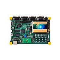
KIT DEVELOPMENT I.MX257, ARM926
Manufacturer
Freescale Semiconductor
Series
i.MX25r
Type
MCUr
Datasheets
1.MCIMX25WPDKJ.pdf
(2 pages)
2.IAR-KSK-IMX25.pdf
(154 pages)
3.IAR-KSK-IMX25.pdf
(2 pages)
4.IAR-KSK-IMX25.pdf
(57 pages)
Specifications of IAR-KSK-IMX25
Contents
Board, Cables, CD, Debugger, Power Supply
Processor To Be Evaluated
I.MX257
Processor Series
i.MX25
Data Bus Width
16 bit
Interface Type
UART, JTAG, USB, Ethernet, SD/MMC
Core
ARM926EJ-S
Silicon Manufacturer
Freescale
Core Architecture
ARM
Core Sub-architecture
ARM9
Silicon Core Number
I.MX2
Silicon Family Name
I.MX25
Mcu Supported Families
I.MX25
For Use With/related Products
i.MX25
Lead Free Status / RoHS Status
Lead free / RoHS Compliant


1
2
3.7.19.1.2
Figure 86
Table 87
1
2
3.7.19.2
The following subsections describe the UART transmit and receive timing in IrDA mode.
3.7.19.2.3
Figure 87
Table 88
116
–
F
T
Note: The UART receiver can tolerate 1/(16 × F
not exceed 3/(16 × F
F
(output)
ref_clk
baud_rate
baud_rate
UA2
TXD
UA1
(input)
ID
ID
RXD
: The period of UART reference clock ref_clk ( ipg_perclk after RFDIV divider).
describes the timing parameter (UA2) shown in the figure.
describes the timing parameters (UA3–UA4) shown in the figure.
: Baud rate frequency. The maximum baud rate the UART can support is ( ipg_perclk frequency)/16.
: Baud rate frequency. The maximum baud rate the UART can support is ( ipg_perclk frequency)/16.
shows the UART receive timing in RS-232 serial mode, showing only 8 data bits and 1 stop bit.
depicts the UART transmit timing in IrDA mode, showing only 8 data bits and 1 stop bit.
UART Infrared (IrDA) Mode Timing
Start
Bit
UART Receive Timing in RS-232 Serial Mode
UART IrDA Mode Transmit Timing
Transmit Bit Time
Start
UA2
Bit
UA3
Parameter
i.MX25 Applications Processor for Consumer and Industrial Products, Rev. 8
baud_rate
Table 86. UART RS-232 Serial Mode Transmit Timing Parameters
Table 87. UART RS-232 Serial Mode Receive Timing Parameters
Figure 86. UART RS-232 Serial Mode Receive Timing Diagram
Bit 0
Receive bit time
Bit 0
Parameter
).
Figure 87. UART IrDA Mode Transmit Timing Diagram
Bit 1
Bit 1
Symbol
1
t
Bit 2
Tbit
Bit 2
baud_rate
UA3
UA2
Bit 3
1/F
) tolerance in each bit. But accumulation tolerance in one frame must
Bit 3
baud_rate
Bit 4
Symbol
t
Rbit
Min.
1
Bit 4
Bit 5
– T
1/F
ref_clk
baud_rate
× F
Bit 6
UA4
2
Bit 5
baud_rate
Min.
2
Bit 7
– 1/(16
1/F
)
Bit 6
baud_rate
Possible
Par Bit
Parity
UA2
1/F
Bit
Max.
baud_rate
× F
Bit 7
+ T
baud_rate
STOP
Max.
Freescale Semiconductor
UA2
BIT
UA3
ref_clk
+ 1/(16
Possible
)
Parity
Bit
Next
Start
Bit
UA3
Units
Units
—
STOP
—
BIT
Related parts for IAR-KSK-IMX25
Image
Part Number
Description
Manufacturer
Datasheet
Request
R

Part Number:
Description:
Manufacturer:
Freescale Semiconductor, Inc
Datasheet:
Part Number:
Description:
Manufacturer:
Freescale Semiconductor, Inc
Datasheet:
Part Number:
Description:
Manufacturer:
Freescale Semiconductor, Inc
Datasheet:
Part Number:
Description:
Manufacturer:
Freescale Semiconductor, Inc
Datasheet:
Part Number:
Description:
Manufacturer:
Freescale Semiconductor, Inc
Datasheet:
Part Number:
Description:
Manufacturer:
Freescale Semiconductor, Inc
Datasheet:
Part Number:
Description:
Manufacturer:
Freescale Semiconductor, Inc
Datasheet:
Part Number:
Description:
Manufacturer:
Freescale Semiconductor, Inc
Datasheet:
Part Number:
Description:
Manufacturer:
Freescale Semiconductor, Inc
Datasheet:
Part Number:
Description:
Manufacturer:
Freescale Semiconductor, Inc
Datasheet:
Part Number:
Description:
Manufacturer:
Freescale Semiconductor, Inc
Datasheet:
Part Number:
Description:
Manufacturer:
Freescale Semiconductor, Inc
Datasheet:
Part Number:
Description:
Manufacturer:
Freescale Semiconductor, Inc
Datasheet:
Part Number:
Description:
Manufacturer:
Freescale Semiconductor, Inc
Datasheet:
Part Number:
Description:
Manufacturer:
Freescale Semiconductor, Inc
Datasheet: