IAR-KSK-IMX25 Freescale Semiconductor, IAR-KSK-IMX25 Datasheet - Page 96
IAR-KSK-IMX25
Manufacturer Part Number
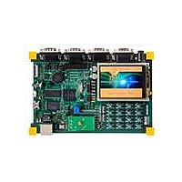
IAR-KSK-IMX25
Description
KIT DEVELOPMENT I.MX257, ARM926
Manufacturer
Freescale Semiconductor
Series
i.MX25r
Type
MCUr
Datasheets
1.MCIMX25WPDKJ.pdf
(2 pages)
2.IAR-KSK-IMX25.pdf
(154 pages)
3.IAR-KSK-IMX25.pdf
(2 pages)
4.IAR-KSK-IMX25.pdf
(57 pages)
Specifications of IAR-KSK-IMX25
Contents
Board, Cables, CD, Debugger, Power Supply
Processor To Be Evaluated
I.MX257
Processor Series
i.MX25
Data Bus Width
16 bit
Interface Type
UART, JTAG, USB, Ethernet, SD/MMC
Core
ARM926EJ-S
Silicon Manufacturer
Freescale
Core Architecture
ARM
Core Sub-architecture
ARM9
Silicon Core Number
I.MX2
Silicon Family Name
I.MX25
Mcu Supported Families
I.MX25
For Use With/related Products
i.MX25
Lead Free Status / RoHS Status
Lead free / RoHS Compliant


1
3.7.14
Each SIM module interface consists of a total of 12 pins (two separate ports, each containing six signals).
Typically a port uses five signals.
The interface is designed to be used with synchronous SIM cards, meaning the SIM module provides the
clock used by the SIM card. The clock frequency is typically 372 times the Tx/Rx data rate; however, the
SIM module can also work with CLK frequencies of 16 times the Tx/Rx data rate.
There is no timing relationship between the clock and the data. The clock that the SIM module provides
to the SIM card is used by the SIM card to recover the clock from the data in the same manner as standard
UART data exchanges. All six signals (five for bidirectional Tx/Rx) of the SIM module are asynchronous
with each other.
There are no required timing relationships between signals in normal mode. The SIM card is initiated by
the interface device; the SIM card responds with Answer to Reset. Although the SIM interface has no
defined requirements, the ISO/IEC 7816 defines reset and power-down sequences (for detailed
information see ISO/IEC 7816).
96
CL of PWMO = 30 pF
Ref No.
2a
2b
3a
3b
4a
4b
1
Subscriber Identity Module (SIM) Timing
i.MX25 Applications Processor for Consumer and Industrial Products, Rev. 8
PWM Source Clock
System CLK frequency
PWM Output
Output setup time
Output delay time
Clock high time
Clock rise time
Clock low time
Clock fall time
Parameter
Table 73. PWM Output Timing Parameter
Figure 67. PWM Timing
1
4a
2a
2b
Minimum
12.29
9.91
8.71
—
—
—
0
3a
1
Maximum
ipg_clk
9.37
0.5
0.5
3b
—
—
—
4b
Freescale Semiconductor
MHz
Unit
ns
ns
ns
ns
ns
ns
Related parts for IAR-KSK-IMX25
Image
Part Number
Description
Manufacturer
Datasheet
Request
R

Part Number:
Description:
Manufacturer:
Freescale Semiconductor, Inc
Datasheet:
Part Number:
Description:
Manufacturer:
Freescale Semiconductor, Inc
Datasheet:
Part Number:
Description:
Manufacturer:
Freescale Semiconductor, Inc
Datasheet:
Part Number:
Description:
Manufacturer:
Freescale Semiconductor, Inc
Datasheet:
Part Number:
Description:
Manufacturer:
Freescale Semiconductor, Inc
Datasheet:
Part Number:
Description:
Manufacturer:
Freescale Semiconductor, Inc
Datasheet:
Part Number:
Description:
Manufacturer:
Freescale Semiconductor, Inc
Datasheet:
Part Number:
Description:
Manufacturer:
Freescale Semiconductor, Inc
Datasheet:
Part Number:
Description:
Manufacturer:
Freescale Semiconductor, Inc
Datasheet:
Part Number:
Description:
Manufacturer:
Freescale Semiconductor, Inc
Datasheet:
Part Number:
Description:
Manufacturer:
Freescale Semiconductor, Inc
Datasheet:
Part Number:
Description:
Manufacturer:
Freescale Semiconductor, Inc
Datasheet:
Part Number:
Description:
Manufacturer:
Freescale Semiconductor, Inc
Datasheet:
Part Number:
Description:
Manufacturer:
Freescale Semiconductor, Inc
Datasheet:
Part Number:
Description:
Manufacturer:
Freescale Semiconductor, Inc
Datasheet: