IAR-KSK-IMX25 Freescale Semiconductor, IAR-KSK-IMX25 Datasheet - Page 70
IAR-KSK-IMX25
Manufacturer Part Number
IAR-KSK-IMX25
Description
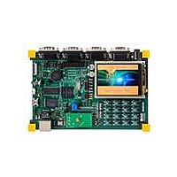
KIT DEVELOPMENT I.MX257, ARM926
Manufacturer
Freescale Semiconductor
Series
i.MX25r
Type
MCUr
Datasheets
1.MCIMX25WPDKJ.pdf
(2 pages)
2.IAR-KSK-IMX25.pdf
(154 pages)
3.IAR-KSK-IMX25.pdf
(2 pages)
4.IAR-KSK-IMX25.pdf
(57 pages)
Specifications of IAR-KSK-IMX25
Contents
Board, Cables, CD, Debugger, Power Supply
Processor To Be Evaluated
I.MX257
Processor Series
i.MX25
Data Bus Width
16 bit
Interface Type
UART, JTAG, USB, Ethernet, SD/MMC
Core
ARM926EJ-S
Silicon Manufacturer
Freescale
Core Architecture
ARM
Core Sub-architecture
ARM9
Silicon Core Number
I.MX2
Silicon Family Name
I.MX25
Mcu Supported Families
I.MX25
For Use With/related Products
i.MX25
Lead Free Status / RoHS Status
Lead free / RoHS Compliant


1
3.7.6.3
Figure 38
(WE1–WE27) shown in the figure.
All WEIM output control signals may be asserted and negated by internal clock relative to BCLK rising
edge or falling edge according to corresponding assertion/negation control fields. Address always begins
relative to BCLK falling edge, but may be ended on rising or falling edge in muxed mode according to the
control register configuration. Output data begins relative to BCLK rising edge except in muxed mode,
where rising or falling edge may be used according to the control register configuration. Input data, ECB
and DTACK are all captured relative to BCLK rising edge.
70
The Flash clock maximum frequency is 50 MHz.
NF10
NF11
NF12
NF13
NF14
NF15
NF16
NF17
NF5
NF6
NF7
NF8
NF9
ID
depicts the timing of the WEIM module, and
NF_WP pulse width
NFALE setup time
NFALE hold time
Data setup time
Data hold time
Write cycle time
NFWE hold time
Ready to NFRE low
NFRE pulse width
READ cycle time
NFRE high hold time
Data setup on read
Data hold on read
Wireless External Interface Module (WEIM) Timing
For timing purposes, transition to signal high is defined as 80% of signal
value; while signal low is defined as 20% of signal value.
Timing for HCLK is 133 MHz. The internal NFC clock (Flash clock) is
approximately 33 MHz (30 ns). All timings are listed according to this NFC
clock frequency (multiples of NFC clock phases), except NF16 and NF17,
which are not related to the NFC clock.
Parameter
i.MX25 Applications Processor for Consumer and Industrial Products, Rev. 8
Table 55. NFC Timing Parameters
Symbol
tREH
tDSR
tDHR
tALH
tALS
tWC
tWP
tWH
tDH
tRR
tRC
tDS
tRP
21T–10 ns
T–3.0 ns
T–5.0 ns
T = NFC Clock Cycle
2T ns
Min.
1.5T
2T
NOTE
T
0.5T–2.5 ns
T–1.5 ns
T–2.5 ns
Timing
N/A
N/A
2T
Table 56
Max.
—
—
—
—
—
—
—
1
(continued)
describes the timing parameters
NFC Clock
Example Timing for
Min.
12.5
620
30
27
60
25
45
60
10
0
T = 30 ns
28.5
27.5
60
Freescale Semiconductor
≈
33 MHz
Max.
—
—
—
—
—
—
—
—
—
—
Unit
ns
ns
ns
ns
ns
ns
ns
ns
ns
ns
ns
ns
ns
Related parts for IAR-KSK-IMX25
Image
Part Number
Description
Manufacturer
Datasheet
Request
R

Part Number:
Description:
Manufacturer:
Freescale Semiconductor, Inc
Datasheet:
Part Number:
Description:
Manufacturer:
Freescale Semiconductor, Inc
Datasheet:
Part Number:
Description:
Manufacturer:
Freescale Semiconductor, Inc
Datasheet:
Part Number:
Description:
Manufacturer:
Freescale Semiconductor, Inc
Datasheet:
Part Number:
Description:
Manufacturer:
Freescale Semiconductor, Inc
Datasheet:
Part Number:
Description:
Manufacturer:
Freescale Semiconductor, Inc
Datasheet:
Part Number:
Description:
Manufacturer:
Freescale Semiconductor, Inc
Datasheet:
Part Number:
Description:
Manufacturer:
Freescale Semiconductor, Inc
Datasheet:
Part Number:
Description:
Manufacturer:
Freescale Semiconductor, Inc
Datasheet:
Part Number:
Description:
Manufacturer:
Freescale Semiconductor, Inc
Datasheet:
Part Number:
Description:
Manufacturer:
Freescale Semiconductor, Inc
Datasheet:
Part Number:
Description:
Manufacturer:
Freescale Semiconductor, Inc
Datasheet:
Part Number:
Description:
Manufacturer:
Freescale Semiconductor, Inc
Datasheet:
Part Number:
Description:
Manufacturer:
Freescale Semiconductor, Inc
Datasheet:
Part Number:
Description:
Manufacturer:
Freescale Semiconductor, Inc
Datasheet: