103H8221-5141/1 SANYO DENKI - SANMOTION, 103H8221-5141/1 Datasheet
103H8221-5141/1
Specifications of 103H8221-5141/1


Related parts for 103H8221-5141/1


103H8221-5141/1 Summary of contents
Page 1
STEPPING SYSTEMS Stepping Systems ...
Page 2
Safety Consideration The PM drivers and stepping motors are the products designed to be used for the general industrial devices. When using those, pay enough attention to the following points. ・Read thoroughly the Operation Manual prior to placement, assembly and/or ...
Page 3
DANGER <General matters> not use the product in an explosive, flammable or corrosive atmosphere, watery place or near a combustible material. Doing so may cause injury or fire. 2. Have a person with expert knowledge for performing the ...
Page 4
Confirm the rotating direction before connecting with the mechanical device. Failure may cause injury or a breakdown. 20. Do not touch the motor output spindle (including the key slot and gears) with a bare hand. Doing ...
Page 5
4 ...
Page 6
STEPPING DRIVER The 2-phase Stepping System Stepping System Configuration Upper PLC DRIVER MOTOR 59 ~ 120 P P Options With encoder With harmonic gear 5 Controller * Refer to the pages of driver for cable. 58 ...
Page 7
Driver Area Chart Source voltage AC100V/115V AC100V DC24V/36V PMM-MD-23210-10,PMM-MD-23211-10 Unipolar type/Micro step specification □ 35mm ( □ 1.10 inch) ( □ 1.38 inch) ( □ PMM-BA-4803-1 PMM-BA-4804-1 Applicable motors Source input AC100/115V Bipolar type ...
Page 8
... PMM-BA-4804-1 Dimensions of Stepping motor model number stepping motor Single shaft 103H7821-1740 103H7821-1710 □ 60mm 103H7822-1740 103H7822-1710 (2.36inch) 103H7823-1740 103H7823-1710 103H8221-5241 103H8221-5211 ø 86mm 103H8222-5241 103H8222-5211 (3.39inch) 103H8223-5241 103H8223-5211 ø 106mm 103H89222-5241 103H89222-5211 103H89223-5241 103H89223-5211 (2.36inch) • For information about the general specifications and dimensions of each stepping motor, refer to its page. ...
Page 9
Specifications of PM Driver Item Input source Source current Rated current 2A/phase (Changeable to 1A/phase, refer to Page 11) Operating ambient temperature 0~+50˚C Conservation temperature -20~+70˚C Operating ambient humidity 35~85%RH (no condensation) 10~90%RH (no condensation) Conservation humidity Vibration resistance 4.9m/s ...
Page 10
Operation, Connection, and Function Input circuit configuration (CW, CCW) --- ● + Photo coupler 330Ω Approx.15mA Input signal - R PM driver Input signal specifications 5µs MIN 4.0~5.5V Rotation 0~0.5V 1µs MAX. 1µs MAX. Timing of command pulse ...
Page 11
Operation, Connection, and Function PM deriver component names and function selection/setting ● PMM-BA-4803-1 PMM-BA-4803 SWH SWL POWER MON EX1 EX2 F RUN ...
Page 12
Operation, Connection, and Function 3 Step angle setting rotary switch (SWH, SWL) Capable to set step angle by the rotary switches SWH and SWL (mode 2). Fundamental Formula Step angle = n/N x Basic step angle of the stepping motor. ...
Page 13
Dimensions [Unit:mm(inch)] PMM-BA-4803-1 4(.16) 47 MAX. (1.85) PMM-BA-4803 SWH SWL POWER MON PM AL EX1 EX2 2 E RUN STP AC100/115V ~ PMM-BA-4804-1 108 ...
Page 14
Pulse Rate-Torque Characteristics/Pulse Rate-Power Current Characteristics PMM-BA-4803-1 ●103H5205-42□□:100V 0.1 1 Pulse rate (kpulse/s) 1-division 100 1000 2000 3000 ...
Page 15
... Source voltage: AC100V, Operating current : 4A/phase Pull-Out torque [J =2.6x10 L1 Source current (TL=MAX), ●103H8221-52□□:100V 700 9 600 500 400 5 300 200 100 100 0.1 1-division 100 ...
Page 16
Pulse Rate-Torque Characteristics/Pulse Rate-Power Current Characteristics PMM-BA-4804-1 ●103H8222-52□□:100V 5 50 700 600 4 40 500 3 30 400 300 2 20 200 1 10 100 0.1 1 Pulse rate (kpulse/s) 1-division 100 1000 2000 3000 ...
Page 17
ø ø 106 16 ...
Page 18
... For information about the general specifications and dimensions of each stepping motor, refer to its page. PMM-UA-4304-1 Dimensions of Stepping motor model number stepping motor Single shaft 103H8221-09411 103H8221-09111 86mm ø 103H8222-09411 103H8222-09111 (3.39inch) 103H8223-09411 103H8223-09111 106mm 103H89222-0941 103H89222-0911 ø ...
Page 19
Specifications of PM Driver Item Input source Source current Rated current 2A/phase (Changeable to 1.2A/phase, refer to Page 20) Operating ambient temperature 0~+50˚C Conservation temperature -20~+70˚C Operating ambient humidity 35~85%RH (no condensation) 10~90%RH (no condensation) Conservation humidity Vibration resistance 4.9m/s ...
Page 20
Operation, Connection, and Function Input circuit configuration (CW, CCW) --- ● + 150Ω Photo coupler + 5V Approx.25mA Input signal - R PM driver Input signal specifications 5µs MIN 4.0~5.5V Rotation 0~0.5V 1µs MAX. 1µs MAX. Timing of the command ...
Page 21
Operation, Connection, and Function PM deriver component names ● PMM-UA-4303-1 2 PMM-UA 1 -4303 + CCW - COM driver mounting screw ~ (For frame grounding output) ...
Page 22
Operation, Connection, and Function PMM-UA-4304 OFF IS3 3 ON IS2 4 IS1 OFF • The factory setting is shown in the figure above. • Turn off the power supply ...
Page 23
Dimensions [Unit:mm(inch)] PMM-UA-4303-1 39 (1.54) PMM-UA -4303 + CCW - COM PMM-UA-4304-1 80 (3.15) PMM-UA-4304 + CCW - COM1 COM2 A ...
Page 24
Pulse Rate-Torque Characteristics/Pulse Rate-Power Current Characteristics PMM-UA-4303-1 ●103H5205-04□□:100V 2 20 250 1.6 16 200 1.2 12 150 0.8 8 100 0 0.1 1 Pulse rate (kpulse/s) Full-step 100 1000 Half-step 100 Number of ...
Page 25
Pulse Rate-Torque Characteristics/Pulse Rate-Power Current Characteristics PMM-UA-4303-1 ●103H6704-04□□:100V Pulse rate (kpulse/s) Full-step 100 1000 2000 ...
Page 26
... Full-step 2000 3000 5000 Half-step 1000 2000 3000 5000 -1 ) Source voltage: AC100V, Operating current : 2A/phase 2 ) Use the rubber coupling] Pull-Out torque [J =0) Source current (T L PMM-UA-4304-1 ●103H8221-09□□:100V 250 8 1 200 6 1.2 12 150 5 4 0.8 8 100 ...
Page 27
Pulse Rate-Torque Characteristics/Pulse Rate-Power Current Characteristics PMM-UA-4304-1 ●103H8222-09□□:100V 5 50 700 600 4 40 500 3 30 400 300 2 20 200 1 10 100 0 Pulse rate (kpulse/s) Full-step 100 1000 2000 ...
Page 28
... For information about the general specifications and dimensions of each stepping motor, refer to its page. 27 DC24V/36V Unipolar type (Applicable motor rated current 1.2A/phase, 2A/phase) Micro-step (Smooth operation and low vibration even at low speeds ...
Page 29
Specifications of PM Driver Photo coupler input method Item PMM-MD- 23210-10 Main power Input source Control power Main power 2A Getaway torque Control power Rated current 1A/phase Operating ambient temperature 0~+50˚C Conservation temperature - 20~+70˚C 35~85% RH (no condensation) Operating ...
Page 30
Operation, Connection, and Function PMM-MD-23210-10(Photo coupler input method) PMM-MD-23220-21(Photo coupler input method) PMM-MD-23220-10(Photo coupler input method) Input circuit configuration (CW, CCW) ● 1(3) 330Ω Photo coupler + 5V Approx.15mA Input signal 2( driver • Pulse duty 50% MAX. ...
Page 31
Operation, Connection, and Function PMM-MD-23210-10(Photo coupler input method) PMM-MD-23220-21(Photo coupler input method) PMM-MD-23220-10(Photo coupler input method) Input circuit configuration (PD) ● 5 330Ω Photo coupler + 5V Approx.15mA 6 Input signal R PM driver • When the crest value of ...
Page 32
Operation, Connection, and Function PM deriver component names ● PMM-MD-23210-10(Photo coupler input method) PMM-MD-23220-21(Photo coupler input method) PMM-MD-23220-10(Photo coupler input method) DWS1 1 CN3 VRI CN1A CN2 Function selection DIP switch pack 1 2 ...
Page 33
Operation, Connection, and Function External wiring diagram ● PMM-MD-23210-10(Photo coupler input method) PMM-MD-23220-21(Photo coupler input method) PMM-MD-23220-10(Photo coupler input method) CN3 DC24V/36V 2 DC24G/36G 1 CN1A 1 Note 2) CW pulse input 2 3 Note 2) CCW pulse input 4 ...
Page 34
Dimensions [Unit:mm(inch)] PMM-MD-23210-10(Photo coupler input method) PMM-MD-23220-21(Photo coupler input method) PMM-MD-23220-10(Photo coupler input method) 1 CN3 5 (.20) 2- ø 4(2- ø .16) Screw holes PMM-MD-23211-10(CMOS input method) PMM-MD-23221-21(CMOS input method) PMM-MD-23221-10(CMOS input method) 5 (.20) 2- ø 4(2- ø ...
Page 35
Pulse Rate-Torque Characteristics/Pulse Rate-Power Current Characteristics PMM-MD-23210-10 PMM-MD-23211-10 ●103H3215-52□□:24V 0.1 1 0.08 0.8 10 0.06 0 0.04 0.4 4 0. Pulse rate (kpulse/s) 1-division 100 1000 ...
Page 36
Pulse Rate-Torque Characteristics/Pulse Rate-Power Current Characteristics PMM-MD-23220-21 PMM-MD-23221-21 ●SH3552-12U□□:24V 0.1 1 Pulse rate (kpulse/s) 1-division 100 1000 2-division 100 ...
Page 37
Pulse Rate-Torque Characteristics/Pulse Rate-Power Current Characteristics PMM-MD-23220-21 PMM-MD-23221-21 ●103H5209-04□□:24V Pulse rate (kpulse/s) 1-division 100 1000 ...
Page 38
Pulse Rate-Torque Characteristics/Pulse Rate-Power Current Characteristics PMM-MD-23220-10 PMM-MD-23221-10 ●103H6703-04□□:24V 1.0 10 140 120 0.8 8 100 0.1 1 Pulse rate (kpulse/s) 1-division 100 1000 2000 ...
Page 39
Pulse Rate-Torque Characteristics/Pulse Rate-Power Current Characteristics PMM-MD-23220-10 PMM-MD-23221-10 ●103H7123-04□□:24V 1.0 10 140 120 0.8 8 100 Pulse rate (kpulse/s) 1-division 100 1000 ...
Page 40
Pulse Rate-Torque Characteristics/Pulse Rate-Power Current Characteristics PMM-MD-23220-10 PMM-MD-23221-10 ●103H7821-04□□:24V 1.0 10 140 120 0.8 8 100 0.1 1 Pulse rate (kpulse/s) 1-division 100 1000 2-division ...
Page 41
... Number of rotations (min -1 ) Source voltage: DC24V, Operating current : 2A/phase - Pull-Out torque [J =15.3x10 kg·m (83.65 oz·in ) Use the rubber coupling] L1 Source current (TL=MAX), Source current (TL= fs: No load maximum starting pulse rate. 1-division is specified ■ ●103H8221-04□□:36V 700 9 600 500 400 5 300 ...
Page 42
Option Pulse Rate-Torque Characteristics/Pulse Rate-Power Current Characteristics Connector set ● PMM-MD-23210-10 (Photo coupler input method) Model Used for Applicable housing:5051-08 I/O signal PM-AP-009 (CN1A) Applicable contact:2759PBGL Applicable housing:5051-06 Applicable contact:5159PBTL Stepping motor PM-AP-053 (CN2) Applicable housing:PHR-6 Applicable contact:SPH-002T-P0.5S Applicable housing:5195-02 ...
Page 43
... Cable 1 (Power source cable) ● Driver side Pin No. Color 1 Black 2 White Cable 2(Power source, signal cable) ● ...
Page 44
Option ● Cable 3 (Signal cable) Driver side Pin No. Color Blue Cable 4(Stepping motor extension cable) ● Driver side Pin No. Color 1 White 2 Black Orange 3 4 Blue 5 ...
Page 45
ø ...
Page 46
... For information about the general specifications and dimensions of each stepping motor, refer to its page. 45 PMM - MD - 23120 - 10 DC24V/36V Unipolar type (Applicable motor rated current 1.2A/phase, 2A/phase) Micro-step (Smooth operation and low vibration even at low speeds ...
Page 47
Specifications of PM Driver Item Input source Source current Rated current Operating ambient temperature Conservation temperature Operating ambient humidity Conservation humidity Vibration resistance Impact resistance Withstand voltage Insulation resistance Mass(Weight) Selection, setting function Signal Name (Brevity code) Pin No. (CN3) ...
Page 48
Operation, Connection, and Function Input circuit configuration (CW, CCW) ● 1 (3) 330Ω Photo coupler + 5V Approx.15mA Input signal R 2 (4) PM driver Input signal specifications 5µs MIN. 4.0~5.5V Rotation 0~0.5V 1µs MAX. 1µs MAX. Timing of command ...
Page 49
Operation, Connection, and Function PM deriver component names ● CN1 CN2 1 M.SEL Operation-current selection rotary switch (RUN) Enable to select operating current value to stepping motor. Dial 0 1 ...
Page 50
Operation, Connection, and Function External wiring diagram ● CN2 DC24V/36V 1 DC24G/36G 2 CN3 1 Note 2) CW pulse input 2 3 Note 2) CCW pulse input 4 5 Step angle selection input 6 7 Power down input 8 Note ...
Page 51
Dimensions [Unit:mm(inch)] 5(.20) 5(.20) Mounting direction and mounting position CN1 CN2 1 M.SEL 82(3.23) 5(.20) 90(3.54) 82(3.23) 5(.20) • Install the PM driver vertically. • As shown in the figure, fix the PM ...
Page 52
Pulse Rate-Torque Characteristics/Pulse Rate-Power Current Characteristics ●103H5205-04□□:24V 0.1 1 Pulse rate (kpulse/s) 1-division 100 1000 2000 3000 5000 ...
Page 53
Pulse Rate-Torque Characteristics/Pulse Rate-Power Current Characteristics fs: No load maximum starting pulse rate. ●103H5210-04□□:24V Pulse ...
Page 54
Pulse Rate-Torque Characteristics/Pulse Rate-Power Current Characteristics ●103H6704-04□□:24V 1 10 140 120 0.8 8 100 0.1 1 Pulse rate (kpulse/s) 1-division 100 1000 2-division 100 Number ...
Page 55
Pulse Rate-Torque Characteristics/Pulse Rate-Power Current Characteristics ●103H7124-04□□:24V 1 10 140 120 0.8 8 100 Pulse rate (kpulse/s) 1-division 100 1000 2000 3000 ...
Page 56
... Source voltage: DC24V, Operating current : 2A/phase 2 ) Use the rubber coupling] Pull-Out torque [J Source current (TL=MAX), ●103H8221-04□□:36V 700 9 600 500 400 5 300 200 100 ...
Page 57
Pulse Rate-Torque Characteristics/Pulse Rate-Power Current Characteristics fs: No load maximum starting pulse rate. ●103H8222-04□□:24V 5 50 700 600 4 40 500 3 30 400 300 2 20 200 1 10 100 0 Pulse ...
Page 58
... PM-C08S0100-02 I/O signal (CN3) connector cable □□ … is 02, 04, or 07. (Refer to separate table 1.) Model No. of stepping motor cable (Supplement table 1) Model of stepping motor 103H6701-04 103H6703-04 103H6704-04 103H7121-04 103H7123-04 02 103H7124-04 103H7126-04 103H8221-04 103H8222-04 103H8223-04 103H7821-04 04 103H7822-04 103H7823-04 103H5205-04 103H5208-04 07 103H5209-04 103H5210-04 57 ...
Page 59
Option ● Cable 1 (Power cable) Driver side Pin No. Color 1 White 2 Black Cable 2 (Signal cable) ● Driver side Pin No. Color 1 Blue 2 Black 3 Blue 4 Black 5 Blue 6 Black 7 Blue 8 ...
Page 60
STEPPING MOTOR The 2-phase Stepping System Upper DRIVER Refer to the pages driver for cable. * Refer to the pages of driver for cable. 100 100 0.1 (1.65inch) □ ...
Page 61
・ m Recommendable Refer to the page27. ( 1.10inch) ( □ 65~ 68 (4.53~8.78 oz·in Recommendable Refer to the page7,17, ( 2.20inch) □ ...
Page 62
Specifications Unipolar winding Holding torque at Model 2-phase energization Shingle shaft Double shafts N·m(oz·in) MIN. SH3533-12U40 −12U10 0.12(16.99) SH3537-12U40 −12U10 0.15(21.24) −12U10 SH3552-12U40 0.23(32.57) Dimensions [Unit:mm(inch)] SH3533-12U40(Single shaft) SH3533-12U10(Double shaft) Lead wire:UL1007 CSA,AWG26 ±1 ±1 ±0.5 (.59 ...
Page 63
Pulse Rate - Torque Characteristics ● SH3533-12U40/SH3533-12U10 0.2 2.0 25 0.16 1.6 20 0.12 1.2 Pull-out torque 15 0.08 0.8 10 0. Pulse rate (kpulse/s) 100 1000 2000 3000 5000 Number of ...
Page 64
Specifications Unipolar winding Holding torque at Model 2-phase energization Single shaft Double shaft N·m(oz·in) MIN. 103-4902-0650 0.032(4.53) -0610 Dimensions [Unit:mm(inch)] 103-4902-0650 (Single shaft) 103-4902-0610 (Double shaft) Lead wire UL1430 AWG28 7±1 16.8± 0.2 (.28±.04) (.66±.008) 18± 0.5 (.7±.02) 4 (.16) ...
Page 65
Specifications Unipolar winding Holding torque at Rated Model Resistance 2-phase energization current Ω/phase Single shaft Double shaft N·m(oz·in) MIN. A/phase 103-591-0241 0.1(14.16) 0.85 -0210 Dimensions [Unit:mm(inch)] 103-591-0241 (Single shaft) 103-591-0210 (Double shaft) Lead wire UL3266 AWG26 □42 ±1 ±0.5 15 ...
Page 66
Specifications Unipolar winding · connector type Holding torque at Model 2-phase energization Single shaft Double shafts N·m(oz·in) MIN. 103H3205-5040 -5010 0.032(4.53) 103H3205-5140 -5110 0.032(4.53) -5110 103H3215-5140 0.062(8.78) 103H3215-5240 -5210 0.062(8.78) Unipolar winding · lead wire type Holding torque at Model ...
Page 67
Dimensions [ Unit: mm (inch) ] Dimensions [Unit:mm(inch)] 103H3205-5040/5140 (Single shaft) Applicable connector :JST Mfg.Co.,Ltd Connector 103H3205-5010/5110 (Double shaft) Terminal □28 ±1 ±0.8 ±0 (□1.10 ±.039 ±.031 ±.02 (.39 ) (1.25 ) (.79 ) 4-23 (4-.91 19.5(.76) ...
Page 68
Pulse Rate - Torque Characteristics ● 103H3205-5040/103H3205-5070 0.05 0 0.04 0.4 5 0.03 0.3 4 Pull-out torque 0.02 0.2 2 0.01 0.1 1 Starting torque 0.1 1 Pulse rate ...
Page 69
Pulse Rate - Torque Characteristics ● 103H3205-5770 0.1 1 0.08 0.8 10 0.06 0.6 8 Pull-out torque 0.04 0.4 4 0.02 0.2 2 Starting torque 0 Pulse ...
Page 70
Specifications Unipolar winding Holding torque at Model 2-phase energization Single shaft Double shaft N·m (oz·in)MIN. 103H5205-0440 -0410 0.2(28.32) 103H5208-0440 -0410 0.3(42.48) 103H5209-0440 -0410 0.32(45.31) 103H5210-0440 -0410 0.37(52.39) Bipolar winding Holding torque at Model 2-phase energization Single shaft Double shaft N·m ...
Page 71
Dimensions [Unit:mm(inch)] 103H5205-0440 (Single shaft) Applicable connector (J.S.T. MFG., CO.) Connector : EHR-6 103H5205-0410 (Double shaft) Terminal : SEH-001T-P0.6 □42 ±0.25 ±1 ±0.5 ±0 ±.01 (□1.65 ±.04 ±.02 ±.02 (.59 ) (1.30 ) (.94 ) 4-31 ±0.25 ...
Page 72
Pulse Rate - Torque Characteristics ● 103H5205-0440 0.2 2 Pull-out torque 0 Starting torque 0.1 1 Pulse rate ...
Page 73
Pulse Rate - Torque Characteristics ● 103H5205-5140 Pull-out torque 0 0 Starting torque 0.1 ...
Page 74
Pulse Rate - Torque Characteristics ● 103H5209-4240 Pull-out torque 0 0 Starting torque 0.1 1 Pulse rate (kpulse/s) ...
Page 75
Pulse Rate - Torque Characteristics ● 103H5210-5140 Pull-out torque 0 0 Starting torque 0 ...
Page 76
Specifications Unipolar winding Holding torque at Model 2-phase energization Single shaft Double shaft N·m(oz·in) MIN. 103H6701-0140 -0110 0.28(39.6) -0410 103H6701-0440 0.28(39.6) -0710 103H6701-0740 0.28(39.6) 103H6703-0140 -0110 0.49(69.4) 103H6703-0440 -0410 0.49(69.4) 103H6703-0740 -0710 0.49(69.4) -0110 103H6704-0140 0.53(75.1) -0410 103H6704-0440 0.52(73.6) -0710 ...
Page 77
Dimensions [Unit:mm(inch)] 103H6701-0140/0440/0740 (Single shaft) 103H6701-0110/0410/0710 (Double shaft) Lead wire UL3266 AWG22 ±1 ±0.8 ±0.5 15.5 39.8 20.6 (.61 ±.04 ) (1.57 ±.03 ) (.81 ±.02 ) □50 (□1.97 1.5 4-41 (.06) (4-1.61 25(.98)MAX. 5 (.2) 103H6704-0140/0440/0740/5040 (Single shaft) 103H6704-0110/0410/0710/5010 ...
Page 78
Pulse Rate - Torque Characteristics ● 103H6701-0140 Pull-out torque 0 0.1 1 Starting torque 0.1 1 Pulse rate ...
Page 79
Pulse Rate - Torque Characteristics ● 103H6704-0140 1.0 10 140 120 0.8 8 100 0 0.4 4 Pull-out torque 0 Starting torque 0 ...
Page 80
Specifications Unipolar winding Holding torque at Model 2-phase energization Single shaft Double shaft N·m (oz·in) MIN. 103H7121-0140 -0110 0.39(55.2) 103H7121-0440 -0410 0.39(55.2) 103H7121-0740 -0710 0.39(55.2) 103H7123-0140 -0110 0.83(117.) 103H7123-0440 -0410 0.83(117.5) 103H7123-0740 -0710 0.78(110.5) 103H7124-0140 -0110 0.98(138.8) -0410 103H7124-0440 0.98(138.8) ...
Page 81
Dimensions [Unit:mm(inch)] 103H7121-0140/0440/0740/5040 (Single shaft) 103H7121-0110/0410/0710/5010 (Double shaft) □56± Lead wire UL1430 AWG22 0.5 (□2.20± .02 ) 15.5± 41.8± 1 0.8 (.61± ) (1.65± ) 4-47.14± .04 .03 0.13 20.6± 0.5 (4-1.86± ) .0005 (.81± ) .02 5 26(1.02) MAX. ...
Page 82
Pulse Rate - Torque Characteristics ● 103H7121-0140 Pull-out torque 0 0 Starting torque 0.1 1 Pulse rate ...
Page 83
Pulse Rate - Torque Characteristics ● 103H7124-0140 1.0 10 140 120 0.8 8 100 0 0.4 4 Pull-out torque 0 Starting torque 0 Pulse ...
Page 84
Pulse Rate - Torque Characteristics ● 103H7121-5040 0 0.4 4 Pull-out torque Starting torque 0.1 1 Pulse rate (kpulse/s) ...
Page 85
Pulse Rate - Torque Characteristics ● 103H7123-5040 1.0 10 140 120 0.8 8 100 0 Pull-out torque 0 0.2 2 Starting torque 0 Pulse ...
Page 86
Pulse Rate - Torque Characteristics ● 103H7126-5040 2.0 20 250 1.6 16 200 1.2 12 150 Pull-out torque at J 0.8 8 100 0 Starting torque 0.1 1 Pulse rate (kpulse/s) 100 ...
Page 87
Pulse Rate - Torque Characteristics ● 103H7128-5640 5.0 50 700 600 4.0 40 500 3.0 30 400 300 2.0 20 Pull-out torque 200 10 1.0 100 Starting torque 0 ...
Page 88
Specifications Unipolar winding Holding torque at Model 2-phase energization Single shaft Double shaft N·m (oz·in) MIN. 103H7821-0140 -0110 0.78(110.5) 103H7821-0440 -0410 0.78(110.5) 103H7821-0740 -0710 0.78(110.5) 103H7822-0140 -0110 1.17(165.7) 103H7822-0440 -0410 1.17(165.7) 103H7822-0740 -0710 1.17(165.7) -0110 103H7823-0140 2.1(297.4) 103H7823-0440 -0410 2.1(297.4) ...
Page 89
Dimensions [Unit:mm(inch)] 103H7821-0140/0440/0740 (Single shaft) 103H7821-0110/0410/0710 (Double shaft) 7.5± 0.1 (.3± .004 ) Applicable connector :JST Mfg.Co.,Ltd Connector Terminal Cross section S-S □60± 0.5 (□2.36± ) .02 15.5± 1 44.8± 0.8 20.6± 0.5 4-50± 0.13 (.61± ) (1.76± ) (.81± ...
Page 90
Pulse Rate - Torque Characteristics ● 103H7821-0140 1.0 10 140 120 0.8 8 100 0 Pull-out torque 0 0 Starting torque 0.1 1 Pulse rate ...
Page 91
Pulse Rate - Torque Characteristics ● 103H7823-0140 2.0 20 250 1.6 16 200 1.2 12 150 Pull-out torque 0.8 8 100 0 Starting torque 0 Pulse rate ...
Page 92
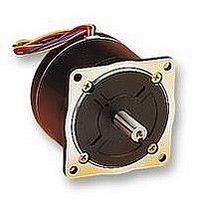
... Bipolar winding Holding torque at Model 2-phase energization Single shaft Double shaft N·m (oz·in) MIN. 103H8221-5041 -5011 2.74(388.0) 103H8221-5141 2.74(388.0) -5111 103H8221-5241 2.74(388.0) -5211 103H8222-5041 -5011 5.09(720.8) 103H8222-5141 -5111 5.09(720.8) 103H8222-5241 -5211 5.09(720.8) 103H8223-5041 -5011 7.44(1053.6) 103H8223-5141 -5111 7 ...
Page 93
... S S Bipolar winding 103H8221/103H8222/103H8223-5□ 41 (Single shaft) 103H8221/103H8222/103H8223-5□ 11 (Double shaft) Lead wire UL1430 28 ±1 L ±0.8 30 ±0.5 (1.10 ±.04 ) (.19 ±.03 ) 4.83 1.52 ±0.5 ±0.25 ±.02 ±.01 (. ...
Page 94
... Pulse rate (kpulse/s) 100 1000 Number of rotations (min Sanyo constant current circuit Source voltage: AC100V Operating current: 2A/phase, 2-phase energization (full-step (83.65 oz·in ) Use the rubber coupling] J =[15.3x10 kg· ● 103H8221-0941 20 250 16 200 L1 12 150 8 100 100 -1 ) Sanyo constant current circuit ...
Page 95
... Sanyo constant current circuit Source voltage: AC100V Operating current: 4A/phase, 2-phase energization (full-step =[15.3x10 kg·m (83.65 oz·in ) Use the rubber coupling =[15.3x10 kg·m (83.65 oz·in ) Use the direct coupling] L2 ● 103H8221-5141 5 50 700 600 4 40 500 3 30 400 L1 300 2 20 200 1 10 100 0 ...
Page 96
Pulse Rate - Torque Characteristics ● 103H8223-5041 10 100 1400 1200 8 80 1000 6 60 800 Pull-out torque at J 600 4 40 400 2 20 200 Starting torque 0.1 1 Pulse rate (kpulse/s) ...
Page 97
96 ...
Page 98
Specifications Unipolar winding Holding torque at Model 2-phase energization Single shaft Double shaft N·m (oz·in) MIN. 103H89222-0941 -0911 10.8(1529.4) 103H89223-0941 -0911 15.5(2194.9) Bipolar winding Holding torque at Model 2-phase energization Single shaft Double shaft N·m (oz·in) MIN. 103H89222-5241 -5211 13.2(1869.2) ...
Page 99
Pulse Rate - Torque Characteristics ● 103H89222-5241 20 200 2500 16 160 2000 12 120 1500 Pull-out torque 1000 4 40 500 Starting torque 0 Pulse rate (kpulse/s) ...
Page 100
Specifications Unipolar winding Holding torque at Model 2-phase energization Single shaft Double shaft N·m(oz·in) MIN. 103H7121-6140 -6110 0.39(55.2) 103H7121-6740 -6710 0.39(55.2) -6110 103H7123-6140 0.83(117.5) -6710 103H7123-6740 0.78(110.5) -6110 103H7126-6140 1.27(179.8) 103H7126-6740 -6710 1.27(179.8) Dimensions [Unit:mm(inch)] 103H7121-6140/6740 (Single shaft) 103H7121-6110/6710 (Double ...
Page 101
Pulse Rate - Torque Characteristics ● 103H7121-6140 Pull-out torque 0 0 Starting torque 0 Pulse ...
Page 102
... Single shaft Double shaft N·m(oz·in) MIN. 103H8221-6240 2.74(388.0) -6210 103H8222-6340 5.09(720.8) -6310 103H8223-6340 -6310 7.44(1053.6) Dimensions [Unit:mm(inch)] 103H8221-6240 (Single shaft) 103H8221-6210 (Double shaft) UL vinyl tube Lead wire UL1430 AWG18 28± 62± 30± 1 0.8 0.5 (1.10± .04 ) (2.4± .03 ) (1.2± ...
Page 103
... Pulse Rate - Torque Characteristics ● 103H8221-6240 5 50 700 600 4 40 500 3 30 400 Pull-out torque at J 300 2 20 200 1 10 Starting torque at J 100 0 Pulse rate (kpulse/s) 100 1000 2000 3000 5000 -1 Number of rotations (min ) Sanyo constant current circuit Source voltage: AC100V Operating current: 6A/phase, 2-phase energization (full-step) ...
Page 104
Specifications Bipolar winding Holding torque at Model 2-phase energization Single shaft Double shaft N·m (oz·in) MIN. 103H89222-6341 -6311 13.2(1869.2) 103H89223-6341 -6311 19(2690.5) Dimensions [Unit:mm(inch)] 103H89222-6341 (Single shaft) 103H89222-6311 (Double shaft) Lead wire UL1430CSA AWG18 28± 1 163.3± 1 (1.1± .04 ...
Page 105
Pulse Rate - Torque Characteristics ● 103H89222-6341 20 200 2500 16 160 2000 12 120 Pull-out torque at J 1500 8 80 1000 4 40 500 Starting torque 0 Pulse rate (kpulse/s) ...
Page 106
Specifications of 2-Phase Stepping Motor General Specifications Insulation class Insulation resistance Withstand voltage Operating environment Winding temperature rise Standing angle error Axial play Radial play (Note 1) Shaft runouts Concentricity of mounting spigot relative to shaft Perpendicularity of mounting surface ...
Page 107
Allowable radial load / thrust load Radial load Frange size Model. No. □28mm(□1.10inch) 103H32□□ □35mm(□1.38inch) SH35□□ □39mm(□1.54inch) 103-49□□ 103H52□□ □42mm(□1.65inch) 103-59□ □50mm(□1.97inch) 103H670□ 103H712□ □56mm(□2.20inch) 103H7128 φ56mm(φ2.20inch) 103-77□□ □60mm(□2.36inch) 103H782□ φ86mm(φ3.39inch) 103H822□ φ106mm(φ4.17inch) 103H8922□ Thrust load Distance from end of ...
Page 108
Internal Wiring and Rotation Direction Unipolar winding ● 103H32 □□ connector pin number (4) Orange (6) ...
Page 109
108 ...
Page 110
Characteristics A constant rotation speed is maintained without slip • within the load range to the motor torque. Enables ultra-low speed rotation and high torque. • Enables cost saving as it operates on the commercial power • supply and therefore ...
Page 111
Specifications Synchronous pull-out torque Rated voltage Rated current Model N·m(oz·in) VAC MIN. 103H7093-0140 0.568(80.4) 100 103H8231-0140 1.6(226.6) 100 103H8232-0240 3(424.8) 220 103H89235-0140 2.6(368.2) 120 103H89236-0140 5.5(778.8) 120 103-830-0140 0.54(76.5) 120 Dimensions [Unit:mm(inch)] 103H7093-0140 Lead wire UL3266 AWG22 □56± 0.5 (□2.2± ...
Page 112
Stepping Motor for Vacuum Environment 1. What Is Stepping Motor for Vacuum Environment We have developed the stepping motor for use under a vacuum environment in response to the demand for the actuator that can operate without a vacuum ...
Page 113
Specifications Holding torque Rated Basic Resistance at 2-phase energization current Model step angle Ω/phase N·m(oz·in) Min A/phase 103-770-12V1 1.8° 0.421(59.6) 2.2 0.73 Dimensions [Unit:mm(inch)] 103-770-12V1 Lead wire: Teflon AWG24 50.8±0.8 20.6± 0.5 Cross section S-S (2±.03) (.8±.02) □56.4± 1.52 (.06) ...
Page 114
Outline The universal controller “PMM8713PT” is the gate array IC (HIC) to control the 2-phase stepping motor drive. This product has been developed for the purpose to further simplify 2-phase stepping motor use, as combined only with switching elements or ...
Page 115
Dimensions [Unit: mm(inch)] Pin No. Name Function 1. C Input pulse UP clock input Input pulse DOWN clock input Input pulse clock input K 4. U/D Rotation direction conversion 5. E energization mode switching ...
Page 116
Electrical Characteristics Measured waveforms on switching time scale C 90 50 ø1~ø4 90 10% tr 90% U/D 10% Function Table Input modes and rotation direction Input Input mode C ...
Page 117
Input Pulse Monitor C U Input Output C O Example of Application Circuit Combined with the power hybrid IC ● GND GND Driving input Energization 5 ...
Page 118
Outline The stepping motor driver IC “PMM2101” monolithic-type power hybrid driver IC (HIC) packaging the circuits for 2- phase stepping motor driving. This product is developed for the purpose to further simplify 2-phase stepping motor use, as combined ...
Page 119
Dimensions [Unit: mm(inch)] Pin No. Name Function 1. V Power terminal for controller section CC2 2. ENA A Enable input terminal 3. ø1 Arm drive input 4. ø2 Arm drive input One shot time constant setting terminal ...
Page 120
Example of Application Circuit 5V + GND 16 1 Driving input mode setting Energization Reset input 9 PMM8713PT Refer to page 113 for the PMM8713PT specifications. ● ● Recommended circuit constants for PMM2101 ...
Page 121
120 ...
Page 122
Outline The Stepping motor driver IC “PMM2301” power hybrid IC (HIC) packaging the integrated excitation mode generation circuits and related switching elements for 2-phase stepping motor driving. This product is developed for the purpose to further simplify 2-phase ...
Page 123
Dimensions [Unit: mm(inch)] Pin No. Terminal name Pin No. Terminal name ー 12. V CC2 2. B 13. V CC2 3. P.GND A 14. Clock 4. P.GND B 15. CW/CCW ー 16. Reset 6. A 17. ...
Page 124
Electrical Characteristics Item Symbol V I Power current CC2 CCO I Effective output current o ave Forward direction voltage of FET diode V df Output saturating voltage V sat V “H” level input voltage IH V “L” level input voltage ...
Page 125
124 ...
Page 126
MEMO 125 ...
Page 127
126 ...
Page 128
Kita-otsuka Toshima-ku Tokyo 170-8451, JAPAN TAIWAN BRANCH Room 401, 4F, No.96, Chung Shan N, Rd., Sec.2, Taipei 104, Taiwan, R.O.C. HONG KONG BRANCH 1109, 11F New East Ocean Centre, 9 Science Museum Road, TST East, Kowloon, Hong Kong SHANGHAI ...