103H8221-5141/1 SANYO DENKI - SANMOTION, 103H8221-5141/1 Datasheet - Page 29
103H8221-5141/1
Manufacturer Part Number
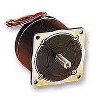
103H8221-5141/1
Description
STEPPER MOTOR, 1.8DEG, 2.4V
Manufacturer
SANYO DENKI - SANMOTION
Datasheet
1.103H8221-51411.pdf
(128 pages)
Specifications of 103H8221-5141/1
Coil Type
Bipolar
Torque Max
2.74N-m
Current Rating
4A
No. Of Phases
2
Resistance
600mohm
Inductance
3.5mH
External Depth
62mm
External Length / Height
82mm
External Width
82mm
Frame Size
34


• Stepping motor rotation in the CW direction means clockwise rotation when facing the output shaft (the flange side) of the stepping motor. CCW direction means
• Set the DIP switch as follows when using the step angle selection function by signal input.
• When the half-step is selected by the step angle selection signal, its torque ought to be 70% of that for the full-step.
Specifications of PM Driver
counterclockwise rotation when facing the same side.
signal (PD)
Step angle
Input signal (CW)
CCW pulse Input
output signal
(Brevity code)
Phase origin
Signal Name
selection
signal (CCW)
(S. SEL)
Power
monitor
CW pulse
down
(U/D)
(MON)
input
input
(CK)
EX1
OFF
Input source
Getaway
torque
Rated current
Operating ambient temperature
Conservation temperature
Operating ambient humidity
Conservation humidity
Vibration resistance
Impact resistance
Withstand voltage
Insulation resistance
Mass(Weight)
Selection, setting
function
Item
Photo coupler
input method
-----
Pin No. (CN1)
1
2
3
4
5
6
7
8
EX2
ON
Main power
Control power
Main power
Control power
CMOS input
method
10
11
7
8
9
EX3
ON
0~+50˚C
- 20~+70˚C
35~85% RH (no condensation)
10~90% RH (no condensation)
4.9m/s
Considering the NDS-C-0110 standard section 3.2.2 division “C”, not influenced.
Not influenced when AC500V is applied between power input terminal and cabinet for one minute.
10MΩ MIN. when measured with DC500V megohmmeter between input terminal and cabinet.
0.18kg(0.4lbs)
Pulse input mode selection-- DIP switches enables selection of Pulse and direction and 2-input mode.
Resolution setting-- DIP switches enables 4 divisions ranging from 1~8 resolution.
Power down --- External signal input enables to turn off the current that flows through the stepping motor.
Automatic current down selection-- Automatic current down function can be selected.
Resolution selection--- External signal input enables to select 1 division (Full-step) and 2 divisions (Half-step)
In the 2-input mode, inputs driving pulses to rotate in CW direction.
In the Pulse and direction mode, inputs driving pulse train to rotate the step motor rotation.
Photo coupler input method, input resistance 330Ω
Input signal voltage: H = 4.0 to 5.5V, L = 0 to 0.5V
Maximum input frequency:20kpulse/s
In the 2-input mode, inputs driving pulses to rotate in CCW direction.
In the Pulse and direction mode, inputs rotation direction signals to the stepping motor.
Internal photo coupler ON (CMOS type: “H” level:) --- CW direction
Internal photo coupler OFF (CMOS type: "L" level)--- CCW direction.
Photo coupler input method, input resistance 330Ω
Input signal voltage: H = 4.0 to 5.5V, L = 0 to 0.5V
Maximum input frequency:20kpulse/s
Inputs PD signal to turn off the current that flows through the stepping motor.
Internal photo coupler ON (CMOS type: “L” level input) --- Power down function is enabled.
Photo coupler input method, input resistance 330Ω
Input signal voltage: H = 4.0 to 5.5V, L = 0 to 0.5V
Indicates ON when the exciting phase is at the origin position.
In the full-step, outputs once for every 4 pulses. In the half-step, outputs once for every 8 pulse
From the photo coupler by the open collector output (ON at the phase origin).
Output specification: Vceo=30V MAX. Ic=5mA MAX.
PMM-MD-
23210-10
1A/phase
2A
2
Frequency range 10~55Hz, Direction: along X,Y and Z axes, for 2 hours each.
Photo coupler input method
1.2A/phase
PMM-MD-
23220-21
(Resolution selection function is only for photo coupler input method type)
-----
2A
-----
PMM-MD-
2A/phase
23220-10
28
3A
DC24V/36V±10%
42
CMOS input method
Input signal voltage: H = 4.0 to 5.5V, L = 0 to 0.5V
Maximum input frequency:20kpulse/s.
CMOS input method
Input signal voltage: H = 4.0 to 5.5V, L = 0 to 0.5V
Maximum input frequency:20kpulse/s.
CMOS input method
Input signal voltage: H = 4.0 to 5.5V, L = 0 to 0.5V
By the input S or SEL signal, the step angle of
full-step or half-step is selected.
“H” level: --- Half-step “L” level --- Full-step
CMOS input method
Input signal voltage: H = 4.0 to 5.5V, L = 0 to 0.5V
From the transistor by the open collector output (ON at the phase origin).
Output specification: Vceo=30V MAX. Ic=5mA MAX.
PMM-MD-
23211-10
1A/phase
2A
50
CMOS input method
1.2A/phase
PMM-MD-
DC5V±5%
23221-21
0.5A
56
2A
60
PMM-MD-
2A/phase
23221-10
3A
ø
86
28
Related parts for 103H8221-5141/1
Image
Part Number
Description
Manufacturer
Datasheet
Request
R

Part Number:
Description:
86MM CIRCULAR 2 PHASE STEPPER MOTOR
Manufacturer:
SANYO DENKI - SANMOTION
Datasheet:

Part Number:
Description:
Stepper Motor Driver
Manufacturer:
SANYO DENKI - SANMOTION
Datasheet:

Part Number:
Description:
MINISTEP BIPOLAR CHOPPER DRIVE, 2, 110 TO 230VAC
Manufacturer:
SANYO DENKI - SANMOTION
Datasheet:

Part Number:
Description:
MINISTEP BIPOLAR CHOPPER DRIVE, 2, 25 TO 45VDC
Manufacturer:
SANYO DENKI - SANMOTION
Datasheet:
Part Number:
Description:
MINISTEP BIPOLAR CHOPPER DRIVE, 2, 25 TO 45VDC
Manufacturer:
SANYO DENKI - SANMOTION
Datasheet:
Part Number:
Description:
MINISTEP BIPOLAR CHOPPER DRIVE, 2, 100 TO 120VAC
Manufacturer:
SANYO DENKI - SANMOTION
Datasheet:

Part Number:
Description:
CONTROLLER, STEPPER, 4 OPTIONAL
Manufacturer:
SANYO DENKI - SANMOTION
Datasheet:

Part Number:
Description:
Stepper Motor
Manufacturer:
SANYO DENKI - SANMOTION
Datasheet:
Part Number:
Description:
Stepper Motor
Manufacturer:
SANYO DENKI - SANMOTION
Datasheet:
Part Number:
Description:
Stepper Motor
Manufacturer:
SANYO DENKI - SANMOTION
Datasheet:
Part Number:
Description:
Stepper Motor
Manufacturer:
SANYO DENKI - SANMOTION
Datasheet:
Part Number:
Description:
Stepper Motor
Manufacturer:
SANYO DENKI - SANMOTION
Datasheet:

Part Number:
Description:
Stepper Motor
Manufacturer:
SANYO DENKI - SANMOTION
Datasheet:
Part Number:
Description:
Stepper Motor
Manufacturer:
SANYO DENKI - SANMOTION
Datasheet:

Part Number:
Description:
Stepper Motor
Manufacturer:
SANYO DENKI - SANMOTION
Datasheet: