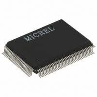
KSZ8893FQL-FX Micrel Inc, KSZ8893FQL-FX Datasheet - Page 42

KSZ8893FQL-FX
Manufacturer Part Number
KSZ8893FQL-FX
Description
2+1 Port 10/100 Switch W/Tranceivers & Frame Buffers, ( )
Manufacturer
Micrel Inc
Datasheet
1.KSZ8893FQL-FX.pdf
(117 pages)
Specifications of KSZ8893FQL-FX
Controller Type
Ethernet Switch Controller
Interface
MII, RMII, SNI
Voltage - Supply
3.1 V ~ 3.5 V
Operating Temperature
-40°C ~ 85°C
Mounting Type
Surface Mount
Package / Case
128-MQFP, 128-PQFP
Number Of Primary Switch Ports
3
Internal Memory Buffer Size
32
Operating Supply Voltage (typ)
3.3V
Fiber Support
Yes
Integrated Led Drivers
Yes
Power Supply Type
Analog/Digital
Package Type
PQFP
Vlan Support
Yes
Operating Temperature (max)
70C
Operating Temperature (min)
0C
Pin Count
128
Mounting
Surface Mount
Jtag Support
No
Operating Temperature Classification
Commercial
Data Rate
1000Mbps
Lead Free Status / RoHS Status
Lead free / RoHS Compliant
For Use With
576-1603 - EVAL KIT EXPERIMENTAL KSZ8893MQL
Current - Supply
-
Lead Free Status / RoHS Status
Compliant, Lead free / RoHS Compliant
Other names
576-3273
Available stocks
Company
Part Number
Manufacturer
Quantity
Price
Company:
Part Number:
KSZ8893FQL-FX
Manufacturer:
Micrel Inc
Quantity:
1 950
Company:
Part Number:
KSZ8893FQL-FX
Manufacturer:
FSC
Quantity:
1 800
Micrel, Inc.
SMI register access is the same as the MIIM register access, except for the register access requirements presented in
this section.
Repeater Mode
The KSZ8893FQL supports repeater mode in 100Base-TX Half Duplex mode. In repeater mode, all ingress packets are
broadcast to the other two ports. MAC address checking and learning are disabled.
Repeater mode is enabled by setting register 6 bit[7] to ‘1’. Prior to setting this bit, all three ports need to be configured
to 100Base-TX Half Duplex mode. Additionally, both PHY ports need to have auto-negotiation disabled.
The latency between the two PHY ports is 270 ns (minimum) and 310 ns (maximum). The 40 ns difference is one clock
skew (one 25 MHz clock period) between reception and transmission. Latency is defined as the time from the first bit of
the Destination Address (DA) entering the ingress port to the first bit of the DA exiting the egress port.
Advanced Switch Functions
Spanning Tree Support
To support spanning tree, port 3 is designated as the processor port.
The other ports (port 1 and port 2), can be configured in one of the five spanning tree states via “transmit enable”,
“receive enable” and “learning disable” register settings in registers 18 and 34 for ports 1 and 2, respectively. The
following table shows the port setting and software actions taken for each of the five spanning tree states.
October 2007
Disable State
The port should not
forward or receive
any packets.
Learning is
disabled.
Blocking State
Only packets to the
processor are
forwarded.
Learning is
disabled.
Listening State
Only packets to
and from the
processor are
forwarded.
Learning is
disabled.
Learning State
Only packets to
and from the
processor are
forwarded.
Learning is
enabled.
Forwarding State
Packets are
forwarded and
received normally.
Learning is
enabled.
Port Setting
“transmit
enable = 0,
receive
enable = 0,
learning
disable =1”
Port Setting
“transmit
enable = 0,
receive
enable = 0,
learning
disable =1”
Port Setting
“transmit
enable = 0,
receive
enable = 0,
learning
disable =1”
Port Setting
“transmit
enable = 0,
receive
enable = 0,
learning
disable = 0”
Port Setting
“transmit
enable = 1,
receive
enable = 1,
learning
disable = 0”
Software Action
The processor should not send any packets to the port. The switch may still send
specific packets to the processor (packets that match some entries in the “static
MAC table” with “overriding bit” set) and the processor should discard those
packets. Address learning is disabled on the port in this state.
Software Action
The processor should not send any packets to the port(s) in this state. The
processor should program the “Static MAC table” with the entries that it needs to
receive (for example, BPDU packets). The “overriding” bit should also be set so that
the switch will forward those specific packets to the processor. Address learning is
disabled on the port in this state.
Software Action
The processor should program the “Static MAC table” with the entries that it needs
to receive (for example, BPDU packets). The “overriding” bit should be set so that
the switch will forward those specific packets to the processor. The processor may
send packets to the port(s) in this state. See “Special Tagging Mode” for details.
Address learning is disabled on the port in this state.
Software Action
The processor should program the “Static MAC table” with the entries that it needs
to receive (for example, BPDU packets). The “overriding” bit should be set so that
the switch will forward those specific packets to the processor. The processor may
send packets to the port(s) in this state. See “Special Tagging Mode” for details.
Address learning is enabled on the port in this state.
Software Action
The processor programs the “Static MAC table” with the entries that it needs to
receive (for example, BPDU packets). The “overriding” bit is set so that the switch
forwards those specific packets to the processor. The processor can send packets
to the port(s) in this state. See “Special Tagging Mode” for details. Address learning
is enabled on the port in this state.
Table 14. Spanning Tree States
42
M9999-101607-1.3
KSZ8893FQL


