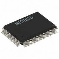
KSZ8893FQL-FX Micrel Inc, KSZ8893FQL-FX Datasheet - Page 86

KSZ8893FQL-FX
Manufacturer Part Number
KSZ8893FQL-FX
Description
2+1 Port 10/100 Switch W/Tranceivers & Frame Buffers, ( )
Manufacturer
Micrel Inc
Datasheet
1.KSZ8893FQL-FX.pdf
(117 pages)
Specifications of KSZ8893FQL-FX
Controller Type
Ethernet Switch Controller
Interface
MII, RMII, SNI
Voltage - Supply
3.1 V ~ 3.5 V
Operating Temperature
-40°C ~ 85°C
Mounting Type
Surface Mount
Package / Case
128-MQFP, 128-PQFP
Number Of Primary Switch Ports
3
Internal Memory Buffer Size
32
Operating Supply Voltage (typ)
3.3V
Fiber Support
Yes
Integrated Led Drivers
Yes
Power Supply Type
Analog/Digital
Package Type
PQFP
Vlan Support
Yes
Operating Temperature (max)
70C
Operating Temperature (min)
0C
Pin Count
128
Mounting
Surface Mount
Jtag Support
No
Operating Temperature Classification
Commercial
Data Rate
1000Mbps
Lead Free Status / RoHS Status
Lead free / RoHS Compliant
For Use With
576-1603 - EVAL KIT EXPERIMENTAL KSZ8893MQL
Current - Supply
-
Lead Free Status / RoHS Status
Compliant, Lead free / RoHS Compliant
Other names
576-3273
Available stocks
Company
Part Number
Manufacturer
Quantity
Price
Company:
Part Number:
KSZ8893FQL-FX
Manufacturer:
Micrel Inc
Quantity:
1 950
Company:
Part Number:
KSZ8893FQL-FX
Manufacturer:
FSC
Quantity:
1 800
Micrel, Inc.
Register 80 (0x50): My Status 1 (Terminal and Center side)
Register 81 (0x51): My Status 2
October 2007
7-4
Bit
Bit
7
6
5
4
3
2
1
0
3
Name
S7
S6
S5
S4
S3
S2
S1
S0
Name
S15 – S12
S11
R/W
R/W
R/W
R/W
R/W
R/W
RO
RO
RO
RO
RO
RO
Description
H-MC Link speed 1
H-MC Link Option
1 = Terminal MC mode
0 = Center MC mode
Loop back mode indication
1 = In loop back state (CST1, CST2, UST1)
0 = Normal
Loss of optical signal notification
1 = Use FEFI
0 = Use maintenance frame
(Center side - CPU will update this bit.
Terminal side - Hardware will update this bit based on external
pin value.)
DIAG result
1 = Diagnostic Fail
0 = Normal operation
(Center side - CPU will update this bit.
Terminal side - This bit will be updated through DIAGF pin.)
UTP Link Down
1 = Link down
0 = Link up
(Center side - CPU will update this bit.
Terminal side - This bit is read only and updated by hardware.)
SD disable
1 = Abnormal (no optical signal detected)
0 = Normal (optical signal detected)
Power down
1 = Power down
0 = Normal operation
Description
Reserved
Do not change the default values.
For Terminal MC mode, this bit must always be “0”.
For Center MC mode, this bit indicates the number of physical
interface(s) making up the UTP link
0 = One
1 = Greater than one
86
M9999-101607-1.3
DIAGF pin
value
DIAGF (Ipd)
FXSD1 pin
value is polled.
Inverse of
PDD# pin
value
PDD# (Ipu)
(Terminal side)
(Center side)
KSZ8893FQL
Default
Default
0x0
0
1
0
0
0
1
0


