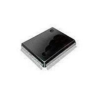
SAA7115HLBE NXP Semiconductors, SAA7115HLBE Datasheet - Page 119

SAA7115HLBE
Manufacturer Part Number
SAA7115HLBE
Description
Video ICs ADV DGTL VIDEO DECODR
Manufacturer
NXP Semiconductors
Datasheet
1.SAA7115HLBE.pdf
(548 pages)
Specifications of SAA7115HLBE
Operating Supply Voltage
3.3 V
Maximum Operating Temperature
+ 70 C
Package / Case
SOT-407
Minimum Operating Temperature
0 C
Mounting Style
SMD/SMT
Number Of Channels
2
Resolution
8 bit
Lead Free Status / RoHS Status
Lead free / RoHS Compliant
Other names
SAA7115HL/V1,557 SAF7115HLBE
- Current page: 119 of 548
- Download datasheet (6Mb)
Philips Semiconductors
Figure 7-18. Message-passing START and END signals.
the first byte of the first line just after the VO_IO2 active
signal.
7.11
In data-streaming and message-passing modes, the
EVO supplies a stream of 8-bit data. No data selection or
data interpretation is done, and data is transferred at the
rate of one byte per VO_CLK. Data is clocked out on the
positive edge of VO_CLK.
When
EVO_ENABLE = 1 and SYNC_STREAMING = 1, the
VO_IO2 signal indicates a data-valid condition. This sig-
nal is asserted when the EVO starts outputting valid data
(that is, data-streaming mode is enabled and video out is
running), and is de-asserted when data-streaming mode
is disabled. As shown in
nal on VO_IO2 is asserted just before the first valid byte
is present on VO_DATA[7:0], and is de-asserted just af-
ter the last valid byte was sent, or if an HBE error is sig-
naled. All transitions of VO_IO2 occur on the rising edge
of VO_CLK. The VO_IO1 signal generates a pulse one
VO_CLK cycle before the first valid data is sent. The
Figure 7-17. Data-streaming valid data signals.
Figure 7-16. Genlock mode.
VO_DATA[7:0]
Image Data
VO_DATA[7:0]
VO_CLK
DATA TRANSFER TIMING
VO_IO1
VO_IO2
data-streaming
VO_CLK
VO_IO2
VO_IO1
VO_IO2
Line 525/625
message
Delay SLAVE_DLY in VO_CLK cycles
Start of
XX
Figure
mode
XX
7-17, the data-valid sig-
D0
EAV
XX
Line 1
is
D1
enabled
D0
D2
D1
Line 2
and
One Frame
D3
DATA_VALID
D2
transitions of VO_IO1 occur on the rising edge of
VO_CLK and last for one VO_CLK cycle.
In message-passing mode, the EVO issues signals on
VO_IO1 and VO_IO2 to indicate the start and end of
messages.
When message passing is started by setting VO_CTL.
VO_ENABLE, the EVO sends a Start condition on
VO_IO1. When the EVO has transferred the contents of
the buffer, it sends an End condition on VO_IO2, sets
BFR1_EMPTY, and interrupts the DSPCPU. The EVO
stops, and no further operation takes place until the
DSPCPU sets VO_ENABLE again to start another mes-
sage, or until the DSCPU initiates other EVO operation.
The timing for these signals is shown in
7.12
7.12.1
The EVO accepts memory-resident video image data in
three formats: YUV 4:2:2 co-sited, YUV 4:2:2 inter-
spersed, and YUV 4:2:0. These formats are shown in
Figure 7-19
PRELIMINARY SPECIFICATION
D4
Line counter loaded by FRAME_PRESET
Line FRAME_PRESET
EAV
D3
IMAGE DATA MEMORY FORMATS
D5
Video Image Formats
through
D4
D6
Figure
D5
Line 525/625
message
End of
D7
7-21.
Dk
Enhanced Video Out
XX
EAV
Line 1
XX
Figure
XX
XX
7-18.
7-9
Related parts for SAA7115HLBE
Image
Part Number
Description
Manufacturer
Datasheet
Request
R
Part Number:
Description:
Ntsc/pal/secam 9-bit Video Decoder
Manufacturer:
NXP Semiconductors
Datasheet:
Part Number:
Description:
NXP Semiconductors designed the LPC2420/2460 microcontroller around a 16-bit/32-bitARM7TDMI-S CPU core with real-time debug interfaces that include both JTAG andembedded trace
Manufacturer:
NXP Semiconductors
Datasheet:

Part Number:
Description:
NXP Semiconductors designed the LPC2458 microcontroller around a 16-bit/32-bitARM7TDMI-S CPU core with real-time debug interfaces that include both JTAG andembedded trace
Manufacturer:
NXP Semiconductors
Datasheet:
Part Number:
Description:
NXP Semiconductors designed the LPC2468 microcontroller around a 16-bit/32-bitARM7TDMI-S CPU core with real-time debug interfaces that include both JTAG andembedded trace
Manufacturer:
NXP Semiconductors
Datasheet:
Part Number:
Description:
NXP Semiconductors designed the LPC2470 microcontroller, powered by theARM7TDMI-S core, to be a highly integrated microcontroller for a wide range ofapplications that require advanced communications and high quality graphic displays
Manufacturer:
NXP Semiconductors
Datasheet:
Part Number:
Description:
NXP Semiconductors designed the LPC2478 microcontroller, powered by theARM7TDMI-S core, to be a highly integrated microcontroller for a wide range ofapplications that require advanced communications and high quality graphic displays
Manufacturer:
NXP Semiconductors
Datasheet:
Part Number:
Description:
The Philips Semiconductors XA (eXtended Architecture) family of 16-bit single-chip microcontrollers is powerful enough to easily handle the requirements of high performance embedded applications, yet inexpensive enough to compete in the market for hi
Manufacturer:
NXP Semiconductors
Datasheet:
Part Number:
Description:
The XA-S3 device is a member of Philips Semiconductors? XA(eXtended Architecture) family of high performance 16-bitsingle-chip microcontrollers
Manufacturer:
NXP Semiconductors
Datasheet:

Part Number:
Description:
The NXP BlueStreak LH75401/LH75411 family consists of two low-cost 16/32-bit System-on-Chip (SoC) devices
Manufacturer:
NXP Semiconductors
Datasheet:

Part Number:
Description:
The NXP LPC3130/3131 combine an 180 MHz ARM926EJ-S CPU core, high-speed USB2
Manufacturer:
NXP Semiconductors
Datasheet:

Part Number:
Description:
The NXP LPC3141 combine a 270 MHz ARM926EJ-S CPU core, High-speed USB 2
Manufacturer:
NXP Semiconductors

Part Number:
Description:
The NXP LPC3143 combine a 270 MHz ARM926EJ-S CPU core, High-speed USB 2
Manufacturer:
NXP Semiconductors

Part Number:
Description:
The NXP LPC3152 combines an 180 MHz ARM926EJ-S CPU core, High-speed USB 2
Manufacturer:
NXP Semiconductors

Part Number:
Description:
The NXP LPC3154 combines an 180 MHz ARM926EJ-S CPU core, High-speed USB 2
Manufacturer:
NXP Semiconductors


