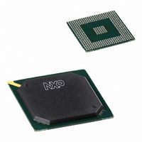
PNX1500E/G,557 NXP Semiconductors, PNX1500E/G,557 Datasheet - Page 215

PNX1500E/G,557
Manufacturer Part Number
PNX1500E/G,557
Description
IC MEDIA PROC 240MHZ 456-BGA
Manufacturer
NXP Semiconductors
Specifications of PNX1500E/G,557
Applications
Multimedia
Core Processor
TriMedia
Controller Series
Nexperia
Interface
I²C, 2-Wire Serial
Number Of I /o
61
Voltage - Supply
1.14 V ~ 1.26 V
Operating Temperature
0°C ~ 85°C
Mounting Type
Surface Mount
Package / Case
456-BGA
Lead Free Status / RoHS Status
Lead free / RoHS Compliant
Program Memory Type
-
Ram Size
-
Lead Free Status / Rohs Status
Compliant
Other names
568-1296
935277746557
PNX1500E/G
935277746557
PNX1500E/G
- Current page: 215 of 828
- Download datasheet (4Mb)
NXP Semiconductors
Volume 1 of 1
PNX15XX_PNX952X_SER_N_4
Product data sheet
Figure 3:
0xFFFF,FFFF
BASE_10
DRAM_BASE
BASE_14
MMIO_BASE
0x0000,0000
BASE_18
XIO_BASE
System Memory Map and Block Diagram Configuration for PNX15xx/952x Series in Host-assisted
Mode
All set by the host BIOS
The PNX15xx/952x Series Boot system also provides a host-assisted boot script for
standalone board system (i.e. not a PCI plug-in card) that use PNX15xx/952x Series
in host-assisted mode. Since the PCI bus of this standalone board system is not
visible by the rest of the world it is possible to assign a default value and let the host
driver recognize a PNX15xx/952x Series system with the following IDs:
Table 9: Host Configuration Sequence
Finally on a PCI bus the sizes for all the apertures must be given an unique physical
addresses at PCI BIOS device enumeration time (DRAM, MMIO and XIO for the
PNX15xx/952x Series). This is the work of the host PCI BIOS driver.
Remark: The aperture sizes are written at boot time into the PCI module MMIO
registers. The host PCI BIOS software retrieves the values by a write, followed by a
read to the PCI Configuration space base address registers. It then assigns a suitable
value to each base address. Refer to [2], Section 6.2.5.1, “Address Maps” for more
details.
A typical simplified board system is sketched in
seen in the
apertures.
8-256 MB DRAM
Boot Script Content
0x1be4_0010
(0x7583<<10) | (dram_size<<7) | en_pci_arb
0x1be4_006c
0x0009_1131
8-128 MB XIO
2 MB MMIO
Figure 3
Rev. 4.0 — 03 December 2007
is an example of how the host BIOS can set the location of the
PCI Agent/Slave
RAM
Host CPU
Bridge
Flash
Comments
PCI Setup Register
Depends on GPIO[11:8]
PCI Subsystem ID is 0x0009
PCI Subsystem Vendor ID is 0x1131
Figure
PNX15xx/952x Series
PCI Agent/Slave
BOOT_MODE[7:0]
DDR SDRAM
3. The aperture allocation
PNX15xx/
Chapter 6: Boot Module
PCI-XIO Bus
PCI Agent/Slave
© NXP B.V. 2007. All rights reserved.
I2C
Boot
EEPROM
(Optional)
6-215
Related parts for PNX1500E/G,557
Image
Part Number
Description
Manufacturer
Datasheet
Request
R

Part Number:
Description:
Manufacturer:
NXP Semiconductors
Datasheet:
Part Number:
Description:
Digital Signal Processors & Controllers - DSP, DSC NEXPERIA MEDIA PROC 240MHZ
Manufacturer:
NXP Semiconductors
Part Number:
Description:
Digital Signal Processors & Controllers - DSP, DSC PNX1500, 240MHZ
Manufacturer:
NXP Semiconductors
Part Number:
Description:
NXP Semiconductors designed the LPC2420/2460 microcontroller around a 16-bit/32-bitARM7TDMI-S CPU core with real-time debug interfaces that include both JTAG andembedded trace
Manufacturer:
NXP Semiconductors
Datasheet:

Part Number:
Description:
NXP Semiconductors designed the LPC2458 microcontroller around a 16-bit/32-bitARM7TDMI-S CPU core with real-time debug interfaces that include both JTAG andembedded trace
Manufacturer:
NXP Semiconductors
Datasheet:
Part Number:
Description:
NXP Semiconductors designed the LPC2468 microcontroller around a 16-bit/32-bitARM7TDMI-S CPU core with real-time debug interfaces that include both JTAG andembedded trace
Manufacturer:
NXP Semiconductors
Datasheet:
Part Number:
Description:
NXP Semiconductors designed the LPC2470 microcontroller, powered by theARM7TDMI-S core, to be a highly integrated microcontroller for a wide range ofapplications that require advanced communications and high quality graphic displays
Manufacturer:
NXP Semiconductors
Datasheet:
Part Number:
Description:
NXP Semiconductors designed the LPC2478 microcontroller, powered by theARM7TDMI-S core, to be a highly integrated microcontroller for a wide range ofapplications that require advanced communications and high quality graphic displays
Manufacturer:
NXP Semiconductors
Datasheet:
Part Number:
Description:
The Philips Semiconductors XA (eXtended Architecture) family of 16-bit single-chip microcontrollers is powerful enough to easily handle the requirements of high performance embedded applications, yet inexpensive enough to compete in the market for hi
Manufacturer:
NXP Semiconductors
Datasheet:
Part Number:
Description:
The XA-S3 device is a member of Philips Semiconductors? XA(eXtended Architecture) family of high performance 16-bitsingle-chip microcontrollers
Manufacturer:
NXP Semiconductors
Datasheet:

Part Number:
Description:
The NXP BlueStreak LH75401/LH75411 family consists of two low-cost 16/32-bit System-on-Chip (SoC) devices
Manufacturer:
NXP Semiconductors
Datasheet:

Part Number:
Description:
The NXP LPC3130/3131 combine an 180 MHz ARM926EJ-S CPU core, high-speed USB2
Manufacturer:
NXP Semiconductors
Datasheet:

Part Number:
Description:
The NXP LPC3141 combine a 270 MHz ARM926EJ-S CPU core, High-speed USB 2
Manufacturer:
NXP Semiconductors

Part Number:
Description:
The NXP LPC3143 combine a 270 MHz ARM926EJ-S CPU core, High-speed USB 2
Manufacturer:
NXP Semiconductors


