TDGL003 Microchip Technology, TDGL003 Datasheet - Page 132
TDGL003
Manufacturer Part Number
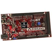
TDGL003
Description
ChipKIT Max32 Development Board PIC32 Boards And Kits
Manufacturer
Microchip Technology
Series
PIC® 32MXr
Type
MCUr
Specifications of TDGL003
Silicon Manufacturer
Microchip
Core Architecture
MIPS
Core Sub-architecture
PIC32
Silicon Core Number
PIC32MX
Silicon Family Name
PIC32MX795Fxxxx
Kit Contents
Board Only
Contents
Board
Lead Free Status / Rohs Status
Lead free / RoHS Compliant
For Use With/related Products
MPLAB®, Arduino™ Mega


PIC32MX3XX/4XX
REGISTER 26-1:
DS61143H-page 132
bit 19-12 PWP<7:0>: Program Flash Write-Protect bits
bit 11-4
bit 3
bit 2
bit 1-0
Prevents selected program Flash memory pages from being modified during code execution. The PWP bits
represent the one’s compliment of the number of write protected program Flash memory pages.
11111111 = Disabled
11111110 = 0xBD00_0FFF
11111101 = 0xBD00_1FFF
11111100 = 0xBD00_2FFF
11111011 = 0xBD00_3FFF
11111010 = 0xBD00_4FFF
11111001 = 0xBD00_5FFF
11111000 = 0xBD00_6FFF
11110111 = 0xBD00_7FFF
11110110 = 0xBD00_8FFF
11110101 = 0xBD00_9FFF
11110100 = 0xBD00_AFFF
11110011 = 0xBD00_BFFF
11110010 = 0xBD00_CFFF
11110001 = 0xBD00_DFFF
11110000 = 0xBD00_EFFF
11101111 = 0xBD00_FFFF
.
.
.
01111111 = 0xBD07_FFFF
Reserved: Write ‘1’
ICESEL: In-Circuit Emulator/Debugger Communication Channel Select bit
1 = PGEC2/PGED2 pair is used
0 = PGEC1/PGED1 pair is used
Reserved: Write ‘1’
DEBUG<1:0>: Background Debugger Enable bits (forced to ‘11’ if code-protect is enabled)
11 = Debugger disabled
10 = Debugger enabled
00 = Reserved (same as ‘11’ setting)
01 = Reserved (same as ‘11’ setting)
DEVCFG0: DEVICE CONFIGURATION WORD 0 (CONTINUED)
© 2011 Microchip Technology Inc.
Related parts for TDGL003
Image
Part Number
Description
Manufacturer
Datasheet
Request
R

Part Number:
Description:
Manufacturer:
Microchip Technology Inc.
Datasheet:
Part Number:
Description:
Manufacturer:
Microchip Technology Inc.
Datasheet:
Part Number:
Description:
Manufacturer:
Microchip Technology Inc.
Datasheet:
Part Number:
Description:
Manufacturer:
Microchip Technology Inc.
Datasheet:
Part Number:
Description:
Manufacturer:
Microchip Technology Inc.
Datasheet:
Part Number:
Description:
Manufacturer:
Microchip Technology Inc.
Datasheet:
Part Number:
Description:
Manufacturer:
Microchip Technology Inc.
Datasheet:
Part Number:
Description:
Manufacturer:
Microchip Technology Inc.
Datasheet: