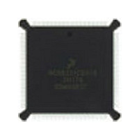
DSP56002FC66 Freescale Semiconductor, DSP56002FC66 Datasheet - Page 102

DSP56002FC66
Manufacturer Part Number
DSP56002FC66
Description
Manufacturer
Freescale Semiconductor
Datasheet
1.DSP56002FC66.pdf
(110 pages)
Specifications of DSP56002FC66
Device Core Size
24b
Architecture
Harvard
Format
Fixed Point
Clock Freq (max)
66MHz
Mips
33
Device Input Clock Speed
66MHz
Ram Size
3KB
Program Memory Size
1.5KB
Operating Supply Voltage (typ)
5V
Operating Supply Voltage (min)
4.5V
Operating Supply Voltage (max)
5.5V
Operating Temp Range
-40C to 105C
Operating Temperature Classification
Industrial
Mounting
Surface Mount
Pin Count
132
Package Type
PQFP
Lead Free Status / Rohs Status
Supplier Unconfirmed
Available stocks
Company
Part Number
Manufacturer
Quantity
Price
Company:
Part Number:
DSP56002FC66
Manufacturer:
MOTOROLA
Quantity:
5 530
Company:
Part Number:
DSP56002FC66
Manufacturer:
MOTOROLA
Quantity:
6 250
Company:
Part Number:
DSP56002FC66
Manufacturer:
MOTOROLA
Quantity:
591
Part Number:
DSP56002FC66
Manufacturer:
MOTOROLA/摩托罗拉
Quantity:
20 000
Company:
Part Number:
DSP56002FC661H72G
Manufacturer:
AD
Quantity:
92
Design Considerations
Heat Dissipation
4-2
estimations obtained from R
performance is adequate, a system level model may be appropriate.
A complicating factor is the existence of three common ways for determining the
junction-to-case thermal resistance in plastic packages:
As noted above, the junction-to-case thermal resistances quoted in this data sheet are
determined using the first definition. From a practical standpoint, that value is also
suitable for determining the junction temperature from a case thermocouple reading
in forced convection environments. In natural convection, using the junction-to-case
thermal resistance to estimate junction temperature from a thermocouple reading on
the case of the package will estimate a junction temperature slightly hotter than
actual temperature. Hence, the new thermal metric, Thermal Characterization
Parameter or
estimate of the junction temperature in natural convection when using the surface
temperature of the package. Remember that surface temperature readings of
packages are subject to significant errors caused by inadequate attachment of the
sensor to the surface and to errors caused by heat loss to the sensor. The
recommended technique is to attach a 40-gauge thermocouple wire and bead to the
top center of the package with thermally conductive epoxy.
Note: Table 2-2 Thermal Characteristics on page 2-2 contains the package thermal
• To minimize temperature variation across the surface, the thermal resistance
• To define a value approximately equal to a junction-to-board thermal
• If the temperature of the package case (T
is measured from the junction to the outside surface of the package (case)
closest to the chip mounting area when that surface has a proper heat sink.
resistance, the thermal resistance is measured from the junction to where the
leads are attached to the case.
the thermal resistance is computed using the value obtained by the equation
(T
values for this chip.
J
– T
T
)/P
JT
, has been defined to be (T
Freescale Semiconductor, Inc.
D
.
For More Information On This Product,
DSP56002/D, Rev. 3
Go to: www.freescale.com
JA
do not satisfactorily answer whether the thermal
J
– T
T
T
)/P
) as determined by a thermocouple,
D
. This value gives a better
MOTOROLA


