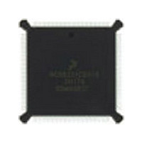
DSP56002FC66 Freescale Semiconductor, DSP56002FC66 Datasheet - Page 107

DSP56002FC66
Manufacturer Part Number
DSP56002FC66
Description
Manufacturer
Freescale Semiconductor
Datasheet
1.DSP56002FC66.pdf
(110 pages)
Specifications of DSP56002FC66
Device Core Size
24b
Architecture
Harvard
Format
Fixed Point
Clock Freq (max)
66MHz
Mips
33
Device Input Clock Speed
66MHz
Ram Size
3KB
Program Memory Size
1.5KB
Operating Supply Voltage (typ)
5V
Operating Supply Voltage (min)
4.5V
Operating Supply Voltage (max)
5.5V
Operating Temp Range
-40C to 105C
Operating Temperature Classification
Industrial
Mounting
Surface Mount
Pin Count
132
Package Type
PQFP
Lead Free Status / Rohs Status
Supplier Unconfirmed
Available stocks
Company
Part Number
Manufacturer
Quantity
Price
Company:
Part Number:
DSP56002FC66
Manufacturer:
MOTOROLA
Quantity:
5 530
Company:
Part Number:
DSP56002FC66
Manufacturer:
MOTOROLA
Quantity:
6 250
Company:
Part Number:
DSP56002FC66
Manufacturer:
MOTOROLA
Quantity:
591
Part Number:
DSP56002FC66
Manufacturer:
MOTOROLA/摩托罗拉
Quantity:
20 000
Company:
Part Number:
DSP56002FC661H72G
Manufacturer:
AD
Quantity:
92
DSP Programming Considerations
MOTOROLA
CANCELLING A PENDING HOST COMMAND EXCEPTION
VARIANCE IN THE HI TIMING
SYNCHRONIZATION OF STATUS BITS FROM HOST TO DSP
READING HF0 AND HF1 AS AN ENCODED PAIR
The host processor may elect to clear the HC bit to cancel the Host Command
Exception request at any time before it is recognized by the DSP. Because the host
does not know exactly when the exception will be recognized (due to exception
processing synchronization and pipeline delays), the DSP may execute the Host
Command Exception after the HC bit is cleared. For these reasons, the HV bits must
not be changed at the same time the HC bit is cleared.
HI timing may vary during initial startup during the time after reset before the PLL
locks. Therefore, before a host attempt to load (i.e., bootstrap) the DSP, the host
should first make sure that the HI port programming has been completed. The
following steps can be used to ensure that the programming is complete:
An alternate method is:
DMA, HF1, HF0, and HCP, HTDE, and HRDF status bits are set or cleared by the host
processor side of the interface. These bits are individually synchronized to the DSP
clock.
Note: Refer to DSP56002 User’s Manual sections describing the I/O Interface and
A potential problem exists when reading status bits HF0 and HF1 as an encoded pair
(i.e., the four combinations 00, 01, 10, and 11 each have significance). A very small
probability exists that the DSP will read the status bits synchronized during
transition. The solution to this potential problem is to read the HF0 and HF1 bits
twice and check for consensus.
1. Set the INIT bit in the ICR
2. Poll the INIT bit until it is cleared.
3. Read the ISR.
1. Write the TREQ/RREQ together with INIT.
2. Poll INIT, ISR, and the HREQ pin.
Host/DMA Interface Programming Model for descriptions of these status
bits.
Freescale Semiconductor, Inc.
For More Information On This Product,
Go to: www.freescale.com
DSP56002/D, Rev. 3
Host Port Considerations
Design Considerations
4-7


