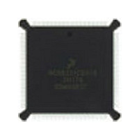
DSP56002FC66 Freescale Semiconductor, DSP56002FC66 Datasheet - Page 12

DSP56002FC66
Manufacturer Part Number
DSP56002FC66
Description
Manufacturer
Freescale Semiconductor
Datasheet
1.DSP56002FC66.pdf
(110 pages)
Specifications of DSP56002FC66
Device Core Size
24b
Architecture
Harvard
Format
Fixed Point
Clock Freq (max)
66MHz
Mips
33
Device Input Clock Speed
66MHz
Ram Size
3KB
Program Memory Size
1.5KB
Operating Supply Voltage (typ)
5V
Operating Supply Voltage (min)
4.5V
Operating Supply Voltage (max)
5.5V
Operating Temp Range
-40C to 105C
Operating Temperature Classification
Industrial
Mounting
Surface Mount
Pin Count
132
Package Type
PQFP
Lead Free Status / Rohs Status
Supplier Unconfirmed
Available stocks
Company
Part Number
Manufacturer
Quantity
Price
Company:
Part Number:
DSP56002FC66
Manufacturer:
MOTOROLA
Quantity:
5 530
Company:
Part Number:
DSP56002FC66
Manufacturer:
MOTOROLA
Quantity:
6 250
Company:
Part Number:
DSP56002FC66
Manufacturer:
MOTOROLA
Quantity:
591
Part Number:
DSP56002FC66
Manufacturer:
MOTOROLA/摩托罗拉
Quantity:
20 000
Company:
Part Number:
DSP56002FC661H72G
Manufacturer:
AD
Quantity:
92
Signal/Pin Descriptions
PLL and Clock
1-6
PINIT
PLOCK
Signal
Name
Output
Signal
Input
Type
Indeter-
during
minate
Reset
Input
State
Table 1-4 PLL and Clock Signals (Continued)
Freescale Semiconductor, Inc.
For More Information On This Product,
PLL Initialization Source—The value of this signal at reset defines
the value written into the PLL Enable (PEN) bit in the PLL control
register.
If PINIT is pulled high during reset, the PEN bit is written as a 1,
enabling the PLL and causing the DSP internal clocks to be derived
from the PLL VCO.
If PINIT is pulled low during reset, the PEN bit is written as a 0,
disabling the PLL and causing DSP internal clocks to be derived
from the clock connected to EXTAL.
PEN is written only at the deassertion of RESET and; therefore, the
value of PINIT is ignored after that time.
Phase and Frequency Lock—This output is generated by an
internal Phase Detector circuit. This circuit drives the output high
when:
The circuit drives the output low (deasserted) whenever the PLL is
enabled, but has not locked onto the proper phase and frequency.
Note:
•
•
DSP56002/D, Rev. 3
Go to: www.freescale.com
the PLL is disabled (the output clock is EXTAL and is
therefore in phase with itself), or
the PLL is enabled and is locked onto the proper phase
(based on the CKP value) and frequency of EXTAL.
PLOCK is a reliable indicator of the PLL lock state only after
the chip has exited the Reset state. During hardware reset,
the PLOCK state is determined by PINIT and the current
PLL lock condition.
Signal Description
MOTOROLA


