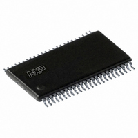
SC28L201A1DGG,112 NXP Semiconductors, SC28L201A1DGG,112 Datasheet - Page 22

SC28L201A1DGG,112
Manufacturer Part Number
SC28L201A1DGG,112
Description
IC UART W/FIFO 48-TSSOP
Manufacturer
NXP Semiconductors
Series
IMPACTr
Datasheet
1.SC28L201A1DGG118.pdf
(110 pages)
Specifications of SC28L201A1DGG,112
Features
False-start Bit Detection
Number Of Channels
2, DUART
Fifo's
256 Byte
Voltage - Supply
3.3V, 5V
With Parallel Port
Yes
With Auto Flow Control
Yes
With False Start Bit Detection
Yes
With Modem Control
Yes
With Cmos
Yes
Mounting Type
Surface Mount
Package / Case
48-TSSOP
Lead Free Status / RoHS Status
Lead free / RoHS Compliant
Other names
568-3293-5
935277824112
SC28L201A1DGG
935277824112
SC28L201A1DGG
Philips Semiconductors
9397 750 13138
Product data sheet
7.4.7.3 Receiver status bits
There are five (5) status bits that are evaluated with each byte (or character) received:
received break, framing error, parity error, overrun error, and change of break. The first
three are appended to each byte and stored in the RxFIFO.
The overrun error and change of break are not necessarily associated with the byte
presently being received. They are developed by the receiver state machine. They will
persist until a command to rest them is issued to the command register. A change of
break occurs on a beginning and the end of a break condition. The meaning of overrun is
that data has not been lost. All data before the overrun flag is set if valid and available.
The receiver status bits are normally cleared by servicing the interrupt condition they
represent or by Rx reset or Rx disable commands or the several error reset commands in
the Command Register (CR).
The ‘received break’ will always be associated with a zero byte in the RxFIFO. It means
that zero character was a break character and not a zero data byte. The reception of a
break condition will always set the ‘change of break’ status bit in the Interrupt Status
Register (ISR).
The ‘change of break’ condition is reset by a reset error status command in the Command
Register.
A framing error occurs when a non-zero character was seen and that character has a zero
in the stop bit position.
The parity error indicates that the receiver-generated parity was not the same as that sent
by the transmitter.
The framing, parity and received break status bits are reset when the associated data byte
is read from the RxFIFO since these ‘error’ conditions are attached to the byte that has the
error.
The overrun error occurs when the RxFIFO is full, the receiver shift register is full, and
another start bit is detected. At this moment the receiver has 257 valid characters and the
start bit of the 258
read a byte from the RxFIFO or the overrun condition will be set. The 258
overruns the 257
RxFIFO is seen (‘seen’ meaning at least one byte was read from the RxFIFO).
Overrun is cleared by a use of the ‘error reset’ command in the Command Register.
The fundamental meaning of the overrun is that data has been lost. Data in the RxFIFO
remains valid. The receiver will begin placing characters in the RxFIFO as soon as a
position becomes vacant.
Remark: Precaution must be taken when reading an overrun FIFO. There will be 256
valid characters in the receiver FIFO. There will be one character in the receiver shift
register. However it will not be known if more than one ‘over-running’ character has been
received since the overrun bit was set. The 257
it will not be known how many characters were lost between the two characters of the
256
numbers 256 and 257 above.
th
and 257
th
reads of the RxFIFO. In the 8-bit mode, the numbers 8 and 9 replace the
th
th
, and the 258
has been seen. At this point the host has approximately
Rev. 01 — 31 October 2005
th
the 259
3.3 V, 5 V UART, 3.125 Mbit/s, with 256-byte FIFO
th
, and so on until an open position in the
th
character received and read as valid but
© Koninklijke Philips Electronics N.V. 2005. All rights reserved.
SC28L201
th
character then
6
16
-bit time to
22 of 110


