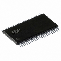
SC28L201A1DGG,112 NXP Semiconductors, SC28L201A1DGG,112 Datasheet - Page 23

SC28L201A1DGG,112
Manufacturer Part Number
SC28L201A1DGG,112
Description
IC UART W/FIFO 48-TSSOP
Manufacturer
NXP Semiconductors
Series
IMPACTr
Datasheet
1.SC28L201A1DGG118.pdf
(110 pages)
Specifications of SC28L201A1DGG,112
Features
False-start Bit Detection
Number Of Channels
2, DUART
Fifo's
256 Byte
Voltage - Supply
3.3V, 5V
With Parallel Port
Yes
With Auto Flow Control
Yes
With False Start Bit Detection
Yes
With Modem Control
Yes
With Cmos
Yes
Mounting Type
Surface Mount
Package / Case
48-TSSOP
Lead Free Status / RoHS Status
Lead free / RoHS Compliant
Other names
568-3293-5
935277824112
SC28L201A1DGG
935277824112
SC28L201A1DGG
Philips Semiconductors
9397 750 13138
Product data sheet
7.4.7.4 Receiver FIFO
7.4.7.5 RxFIFO status bits, status reporting modes
The ‘change of break’ means that either a break has been detected or that the break
condition has been cleared. This bit is available in the ISR. The break change bit being set
in the ISR and the received break bit being set in the SR will signal the beginning of a
break. At the termination of the break condition only the change of break in the ISR will be
set. After the break condition is detected the termination of the break will only be
recognized when the RXD input has returned to the HIGH state for two successive edges
of the 1 clock;
The receiver is disabled by reset or via CR commands. A disabled receiver will not
interrupt the host CPU under any circumstance in the normal mode of operation. If the
receiver is in the multi-drop or special mode, it will be partially enabled and thus may
cause an interrupt. Refer to
The receiver buffer memory is a 256-byte FIFO with three status bits appended to each
data byte. (The FIFO is then 256 11-bit ‘words’.) The receiver state machine gathers the
bits from the Receiver Shift Register and the status bits from the receiver logic and writes
the assembled byte and status bits to the RxFIFO shortly after the stop bit has been
sampled. Logic associated with the FIFO encodes the number of filled positions for
presentation to the interrupt arbitration system. The encoding is always the number of
filled positions. Thus, a full RxFIFO will bid with the value of 255 and the Status Register
RxFULL bit is set. The RxFULL bit means 256 characters. When empty, it will not bid at
all. One position occupied bids with the value ‘1’. An empty FIFO will not bid since no
character is available.
Normally RxFIFO will present a bid to the arbitration system whenever it has one or more
filled positions. The bits of the RxFIFO Interrupt Offset Level (RxFIL) of MR0 allow the
user to modify this characteristic so that bidding will not start until one of four levels has
been reached.
As will be shown later, this feature may be used to make slight improvements in the
interrupt service efficiency. A similar system exists in the transmitter.
This description applies to the upper three bits in the Status Register. These three bits are
not ‘in the status register’; they are part of the RxFIFO. The three status bits at the output
of the RxFIFO are presented as the upper three bits of the Status Register.
The error status of a character, as reported by a read of the SR (status register upper
three bits) can be provided in two ways, as programmed by the error mode control bit in
the mode register: Character mode or the Block mode. The Block mode may be further
modified (via a CR command) to set the status bits as the characters enter the FIFO or as
they are read from the FIFO.
In the Character mode, status is provided on a character-by-character basis as the
characters are read from the RxFIFO: the ‘status’ applies only to the character at the
output of the RxFIFO (the next character to be read).
In the Block mode (on entry), the status provided in the SR for these three bits is the
logical OR of the status for all characters coming to the input of the RxFIFO since the last
reset error command was issued. In this mode each of the status bits stored in the
RxFIFO are passed through a latch as they are sequentially written to the receiver FIFO. If
any of the characters has an error bit set that latch will set and remain set until it is reset
1
2
-bit to 1-bit time (see above).
Rev. 01 — 31 October 2005
Section 8.2.2 “Mode Register 1 (MR1)”
3.3 V, 5 V UART, 3.125 Mbit/s, with 256-byte FIFO
© Koninklijke Philips Electronics N.V. 2005. All rights reserved.
for more information.
SC28L201
23 of 110


