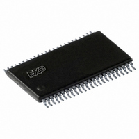
SC28L201A1DGG,112 NXP Semiconductors, SC28L201A1DGG,112 Datasheet - Page 24

SC28L201A1DGG,112
Manufacturer Part Number
SC28L201A1DGG,112
Description
IC UART W/FIFO 48-TSSOP
Manufacturer
NXP Semiconductors
Series
IMPACTr
Datasheet
1.SC28L201A1DGG118.pdf
(110 pages)
Specifications of SC28L201A1DGG,112
Features
False-start Bit Detection
Number Of Channels
2, DUART
Fifo's
256 Byte
Voltage - Supply
3.3V, 5V
With Parallel Port
Yes
With Auto Flow Control
Yes
With False Start Bit Detection
Yes
With Modem Control
Yes
With Cmos
Yes
Mounting Type
Surface Mount
Package / Case
48-TSSOP
Lead Free Status / RoHS Status
Lead free / RoHS Compliant
Other names
568-3293-5
935277824112
SC28L201A1DGG
935277824112
SC28L201A1DGG
Philips Semiconductors
9397 750 13138
Product data sheet
7.4.7.6 Wake-up mode
with a ‘receiver reset’ issued from the Command Register or a chip reset is issued. The
purpose of this mode is indicating an error in the data block as opposed to an error in a
character. This mode improves receiver service efficiency. In modern systems with low
error rates, it is more efficient to ask for retransmit of a block error data than to analyze it
on a byte by byte system.
The above paragraph describes the Block mode activity as the data is entered to the
RxFIFO. Normally the status would be read only once: at the beginning of the service to
the receiver interrupt. If an error is not set then the entire amount of data in the RxFIFO
would be read without any more reading of the receiver status. This effectively doubles the
efficiency of reading the receiver RxFIFO.
The use of the Block mode on Exit passes the data and error conditions as the RxFIFO is
read. Here the final read of the status register would be after the last byte was read from
the RxFIFO. This delays the knowledge of an error condition until after the data has been
read.
The latch used in the block mode to indicate ‘problem data’ is usually set as the
characters are read out of the RxFIFO. Via a command in the CR, the latch may be
configured to set as error characters are loaded to the RxFIFO. This gives the advantage
of indicating ‘problem data’ up to 256 (or the FIFO size) characters earlier.
In either mode, reading the SR does not affect the RxFIFO. The RxFIFO address is
advanced only when the RxFIFO is read. Therefore, the SR should be read prior to
reading the corresponding data character.
If the RxFIFO is full when a new character is received, the character is held in the receiver
shift register until a position is available in the RxFIFO. At this time there are 257 valid
characters in the RxFIFO. If an additional character is received while this state exists, the
contents of the RxFIFO are not affected: the character previously in the shift register is
lost and the overrun error status bit, SR[4], will be set upon receipt of the start bit of the
new (overrunning) character.
(Also referred to as the ‘9-bit’, ‘multi-drop’, ‘party line’ or Special mode.)
In the use of this mode, the parity bit is used to distinguish between an address byte and a
data byte. The purpose is to allow data to be directed to a particular station from a master
station. A station is addressed by a byte with the parity bit set to ‘1’. The data for that
station is sent following the address and all the data bytes have the parity bit set to ‘0’.
The SC28L201 provides four modes of this common asynchronous ‘party line’ protocol
where the parity bit is used to indicate that a byte is address data or information data.
Three automatic modes and the default Host operated mode are provided. The automatic
mode has several sub-modes (see below). In the full automatic mode the internal state
machine devoted to this function will handle all operations associated with address
recognition, data handling, receiver enables and disables. In both modes the meaning of
the parity bit is changed. A ‘1’ usually means address, a ‘0’ means data.
Its purpose is to allow several receivers connected to the same data source to be
individually addressed. Of course addressing could be by group also. Normally the
‘Master’ would send an address byte to all receivers ‘listening’. The remote receiver will be
‘looking’ at the data stream for its address. Upon recognition of its address the receiver
Rev. 01 — 31 October 2005
3.3 V, 5 V UART, 3.125 Mbit/s, with 256-byte FIFO
© Koninklijke Philips Electronics N.V. 2005. All rights reserved.
SC28L201
24 of 110


