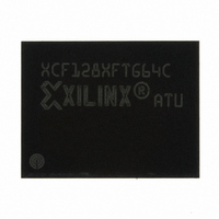
XCF128XFTG64C Xilinx Inc, XCF128XFTG64C Datasheet - Page 22

XCF128XFTG64C
Manufacturer Part Number
XCF128XFTG64C
Description
IC PROM SRL 128M GATE 64-FTBGA
Manufacturer
Xilinx Inc
Datasheet
1.XCF128XFTG64C.pdf
(88 pages)
Specifications of XCF128XFTG64C
Memory Size
128Mb
Programmable Type
In System Programmable
Voltage - Supply
1.7 V ~ 2 V
Operating Temperature
-40°C ~ 85°C
Package / Case
64-TBGA
Access Time
85ns
Supply Voltage Range
1.7V To 2V
Memory Case Style
FTBGA
No. Of Pins
64
Operating Temperature Range
-40°C To +85°C
Svhc
No SVHC (15-Dec-2010)
Package /
RoHS Compliant
Lead Free Status / RoHS Status
Lead free / RoHS Compliant
Other names
122-1578
Available stocks
Company
Part Number
Manufacturer
Quantity
Price
Company:
Part Number:
XCF128XFTG64C
Manufacturer:
XILINX
Quantity:
319
Part Number:
XCF128XFTG64C
Manufacturer:
XILINX/赛灵思
Quantity:
20 000
Controller is active; when the bit is High (set to ‘1’), the
controller is inactive, and the device is ready to process a
new command.
The Program/Erase Controller Status bit is Low immediately
after a Program/Erase Suspend command was issued until
the controller pauses. After the Program/Erase Controller
pauses the bit is High.
Erase Suspend Status Bit (SR6)
The Erase Suspend Status bit indicates that an erase
operation is suspended. When this bit is High (set to ‘1’), a
Program/Erase Suspend command was issued and the
memory is waiting for a Program/Erase Resume command.
The Erase Suspend Status bit should only be considered
valid when the Program/Erase Controller Status bit is High
(Program/Erase Controller inactive). SR6 is set within the
Erase Suspend Latency time of the Program/Erase
Suspend command being issued; therefore, the memory
can still complete the operation rather than entering the
Suspend mode.
When a Program/Erase Resume command is issued, the
Erase Suspend Status bit returns Low.
Erase/Blank Check Status Bit (SR5)
The Erase/Blank Check Status bit is used to identify if an
error occurred during a Block Erase operation. When this bit
is High (set to ‘1’), the Program/Erase Controller applied the
maximum number of pulses to the block and still failed to
verify that it erased correctly.
The Erase/Blank Check Status bit should be read after the
Program/Erase Controller Status bit is High (Program/Erase
Controller inactive).
The Erase/Blank Check Status bit is also used to indicate
whether an error occurred during the Blank Check
operation. If the data at one or more locations in the block
where the Blank Check command was issued is different
from FFFFh, SR5 is set to '1'.
After set High, the Erase/Blank Check Status bit must be set
Low by a Clear Status Register command or a hardware
reset before a new erase command is issued; otherwise, the
new command appears to fail.
Program Status Bit (SR4)
The Program Status bit is used to identify if there is an error
during a program operation. This bit should be read after the
Program/Erase Controller Status bit is High (Program/Erase
Controller inactive).
When the Program Status bit is High (set to ‘1’), the
Program/Erase Controller applied the maximum number of
pulses to the word and still failed to verify that it
programmed correctly.
DS617 (v3.0.1) January 07, 2010
Product Specification
R
Platform Flash XL High-Density Configuration and Storage Device
www.xilinx.com
Attempting to program a '1' to an already programmed bit
while V
V
the attempt is not shown.
After set High, the Program Status bit must be set Low by a
Clear Status Register command or a hardware reset before
a new program command is issued; otherwise, the new
command appears to fail.
V
The V
the V
pin is only sampled at the beginning of a program or erase
operation. Program and erase operations are not
guaranteed if V
When the V
the V
When the V
a voltage below the V
memory is protected and program and erase operations
cannot be performed.
After set High, the V
Status Register command or a hardware reset before a new
program or erase command is issued; otherwise, the new
command appears to fail.
Program Suspend Status Bit (SR2)
The Program Suspend Status bit indicates that a program
operation is suspended. This bit should only be considered
valid when the Program/Erase Controller Status bit is High
(Program/Erase Controller inactive).
When the Program Suspend Status bit is High (set to ‘1’), a
Program/Erase Suspend command was issued, and the
memory is waiting for a Program/Erase Resume command.
SR2 is set within the Program Suspend Latency time of the
Program/Erase Suspend command being issued; therefore,
the memory can still complete the operation rather than
entering the Suspend mode.
When a Program/Erase Resume command is issued, the
Program Suspend Status bit returns Low.
PP
PP
is different from V
PP
PP
Status Bit (SR3)
PP
PP
pin during program and erase operations. The V
pin was sampled at a valid voltage.
Status bit is used to identify an invalid voltage on
= V
PP
PP
PPH
Status bit is High (set to ‘1’), the V
Status bit is Low (set to ‘0’), the voltage on
PP
also sets the Program Status bit High. If
becomes invalid during an operation.
PP
PPH
PP
Status bit must be set Low by a Clear
Lockout Voltage (V
, SR4 remains Low (set to '0'), and
PPLK
). the
PP
pin has
PP
22


