Z16F2800100ZCOG Zilog, Z16F2800100ZCOG Datasheet - Page 112
Z16F2800100ZCOG
Manufacturer Part Number
Z16F2800100ZCOG
Description
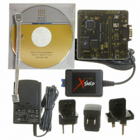
DEV KIT FOR Z16F ZNEO
Manufacturer
Zilog
Series
ZNEO™r
Type
MCUr
Datasheets
1.Z16F2800100ZCOG.pdf
(2 pages)
2.Z16F2800100ZCOG.pdf
(30 pages)
3.Z16F2800100ZCOG.pdf
(388 pages)
Specifications of Z16F2800100ZCOG
Contents
Evaluation Board, Software and Documentation
For Use With/related Products
Z16F Series
For Use With
269-4661 - KIT ACC ETHERNET SMART CABLE
Lead Free Status / RoHS Status
Lead free / RoHS Compliant
Other names
269-4537


Operation
PS022008-0810
Note:
Timer Operating Modes
The general-purpose timer is a 16-bit up-counter. In normal operation, the timer is
initialized to
reload high and low byte registers, then resets to
continues depending on the mode.
Minimum time-out delay (1 system clock) is set by loading the value
Timer Reload High and Low byte registers and setting the prescale value to 1.
Maximum time-out delay (2
the Timer Reload High and Low byte registers and setting the prescale value to 128. When
the timer reaches
If the reload register is set to a value less than the current counter value, the counter
continues counting until it reaches
continues to count until it reaches the reload value and it resets to
When T0IN0, T0IN1, and T0IN2 functions are enabled on the PB0, PB1, and PB2 pins,
each Timer0 input will have the same effect as the single Timer0 Input pin T0IN. For
example, if the Timer 0 is in Capture Mode, any transitions on any of the PB0, PB1, and
PB2 pins will cause a Capture.
The timers are configured to operate in the following modes:
ONE-SHOT Mode
In ONE-SHOT mode, the timer counts up to the 16-bit reload value stored in the Timer
Reload High and Low byte registers. The timer input is the system clock. When the timer
reaches the reload value, it generates an interrupt and the count value in the Timer High
and Low byte registers is reset to
counting.
If the timer output alternate function is enabled, the timer output pin changes state for one
system clock cycle (from Low to High then back to Low if TPOL = 0) at timer Reload. If
the timer output is required to make a permanent state change on ONE-SHOT timeout,
first set the TPOL bit in the timer control 1 register to the start value before beginning
ONE-SHOT mode. Then, after starting the timer, set TPOL to the opposite value.
Follow the steps below to configure a timer for ONE-SHOT mode and initiate the count:
1. Write to the timer control registers to:
–
–
–
Disable the timer.
Configure the timer for ONE-SHOT mode.
Set the prescale value.
0001H
FFFFH
. When the timer is enabled, it counts up to the value contained in the
, the timer rolls over to
P R E L I M I N A R Y
16
* 2
0001H
7
FFFFH
system clocks) is set by loading the value
. The timer is automatically disabled and stops
, and then resets to
0000H
0001H
.
. The counter either halts or
0000H
Product Specification
0001H
ZNEO
. Then the timer
0001H
.
Z16F Series
into the
0000H
Timers
into
97
Related parts for Z16F2800100ZCOG
Image
Part Number
Description
Manufacturer
Datasheet
Request
R

Part Number:
Description:
Communication Controllers, ZILOG INTELLIGENT PERIPHERAL CONTROLLER (ZIP)
Manufacturer:
Zilog, Inc.
Datasheet:

Part Number:
Description:
KIT DEV FOR Z8 ENCORE 16K TO 64K
Manufacturer:
Zilog
Datasheet:

Part Number:
Description:
KIT DEV Z8 ENCORE XP 28-PIN
Manufacturer:
Zilog
Datasheet:

Part Number:
Description:
DEV KIT FOR Z8 ENCORE 8K/4K
Manufacturer:
Zilog
Datasheet:

Part Number:
Description:
KIT DEV Z8 ENCORE XP 28-PIN
Manufacturer:
Zilog
Datasheet:

Part Number:
Description:
DEV KIT FOR Z8 ENCORE 4K TO 8K
Manufacturer:
Zilog
Datasheet:
Part Number:
Description:
CMOS Z8 microcontroller. ROM 16 Kbytes, RAM 256 bytes, speed 16 MHz, 32 lines I/O, 3.0V to 5.5V
Manufacturer:
Zilog, Inc.
Datasheet:
Part Number:
Description:
Low-cost microcontroller. 512 bytes ROM, 61 bytes RAM, 8 MHz
Manufacturer:
Zilog, Inc.
Datasheet:
Part Number:
Description:
Z8 4K OTP Microcontroller
Manufacturer:
Zilog, Inc.
Datasheet:
Part Number:
Description:
CMOS SUPER8 ROMLESS MCU
Manufacturer:
Zilog, Inc.
Datasheet:
Part Number:
Description:
SL1866 CMOSZ8 OTP Microcontroller
Manufacturer:
Zilog, Inc.
Datasheet:
Part Number:
Description:
SL1866 CMOSZ8 OTP Microcontroller
Manufacturer:
Zilog, Inc.
Datasheet:
Part Number:
Description:
OTP (KB) = 1, RAM = 125, Speed = 12, I/O = 14, 8-bit Timers = 2, Comm Interfaces Other Features = Por, LV Protect, Voltage = 4.5-5.5V
Manufacturer:
Zilog, Inc.
Datasheet:
Part Number:
Description:
Manufacturer:
Zilog, Inc.
Datasheet: