C8051F040DK Silicon Laboratories Inc, C8051F040DK Datasheet - Page 298
C8051F040DK
Manufacturer Part Number
C8051F040DK
Description
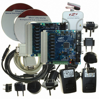
DEV KIT FOR F040/F041/F042/F043
Manufacturer
Silicon Laboratories Inc
Type
MCUr
Specifications of C8051F040DK
Contents
Evaluation Board, Power Supply, USB Cables, Adapter and Documentation
Processor To Be Evaluated
C8051F04x
Interface Type
USB
Silicon Manufacturer
Silicon Labs
Core Architecture
8051
Silicon Core Number
C8051F040
Silicon Family Name
C8051F04x
Lead Free Status / RoHS Status
Contains lead / RoHS non-compliant
For Use With/related Products
Silicon Laboratories C8051 F040, 041, 042, 043 MCUs
Lead Free Status / Rohs Status
Lead free / RoHS Compliant
Other names
336-1205
Available stocks
Company
Part Number
Manufacturer
Quantity
Price
Company:

Part Number:
C8051F040DK
Manufacturer:
SiliconL
Quantity:
9


C8051F040/1/2/3/4/5/6/7
23.2.2. Capture Mode
In Capture Mode, Timer n will operate as a 16-bit counter/timer with capture facility. When the Timer Exter-
nal Enable bit (found in the TMRnCN register) is set to ‘1’, a high-to-low transition on the TnEX input pin
causes the 16-bit value in the associated timer (TMRnH, TMRnL) to be loaded into the capture registers
(RCAPnH, RCAPnL). If a capture is triggered in the counter/timer, the Timer External Flag (TMRnCN.6)
will be set to ‘1’ and an interrupt will occur if the interrupt is enabled. See
dler” on page 153
As the 16-bit timer register increments and overflows TMRnH:TMRnL, the TFn Timer Overflow/Underflow
Flag (TMRnCN.7) is set to ‘1’ and an interrupt will occur if the interrupt is enabled. The timer can be config-
ured to count down by setting the Decrement Enable Bit (TMRnCF.0) to ‘1’. This will cause the timer to
decrement with every timer clock/count event and underflow when the timer transitions from 0x0000 to
0xFFFF. Just as in overflows, the Overflow/Underflow Flag (TFn) will be set to ‘1’, and an interrupt will
occur if enabled.
Counter/Timer with Capture mode is selected by setting the Capture/Reload Select bit CP/RLn
(TMRnCN.0) and the Timer n Run Control bit TRn (TMRnCN.2) to logic 1. The Timer n respective External
Enable EXENn (TMRnCN.3) must also be set to logic 1 to enable captures. If EXENn is cleared, transi-
tions on TnEX will be ignored.
296
External Clock
SYSCLK
(XTAL1)
Tn
TnE
X
Crossbar
8
2
12
Crossbar
for further information concerning the configuration of interrupt sources.
EXENn
Figure 23.4. Tn Capture Mode Block Diagram
TRn
0
1
TMRnCF
M
T
n
1
M
T
n
0
T
O
G
n
Rev. 1.5
O
T
n
E
TCLK
D
C
E
N
RCAPnL
TMRnL
0xFF
RCAPnH
TMRnH
0xFF
Toggle Logic
Section “12.3. Interrupt Han-
CP/RLn
EXENn
EXFn
C/Tn
TRn
TFn
0
1
Interrupt
(Port Pin)
Tn
Related parts for C8051F040DK
Image
Part Number
Description
Manufacturer
Datasheet
Request
R

Part Number:
Description:
SMD/C°/SINGLE-ENDED OUTPUT SILICON OSCILLATOR
Manufacturer:
Silicon Laboratories Inc
Part Number:
Description:
Manufacturer:
Silicon Laboratories Inc
Datasheet:
Part Number:
Description:
N/A N/A/SI4010 AES KEYFOB DEMO WITH LCD RX
Manufacturer:
Silicon Laboratories Inc
Datasheet:
Part Number:
Description:
N/A N/A/SI4010 SIMPLIFIED KEY FOB DEMO WITH LED RX
Manufacturer:
Silicon Laboratories Inc
Datasheet:
Part Number:
Description:
N/A/-40 TO 85 OC/EZLINK MODULE; F930/4432 HIGH BAND (REV E/B1)
Manufacturer:
Silicon Laboratories Inc
Part Number:
Description:
EZLink Module; F930/4432 Low Band (rev e/B1)
Manufacturer:
Silicon Laboratories Inc
Part Number:
Description:
I°/4460 10 DBM RADIO TEST CARD 434 MHZ
Manufacturer:
Silicon Laboratories Inc
Part Number:
Description:
I°/4461 14 DBM RADIO TEST CARD 868 MHZ
Manufacturer:
Silicon Laboratories Inc
Part Number:
Description:
I°/4463 20 DBM RFSWITCH RADIO TEST CARD 460 MHZ
Manufacturer:
Silicon Laboratories Inc
Part Number:
Description:
I°/4463 20 DBM RADIO TEST CARD 868 MHZ
Manufacturer:
Silicon Laboratories Inc
Part Number:
Description:
I°/4463 27 DBM RADIO TEST CARD 868 MHZ
Manufacturer:
Silicon Laboratories Inc
Part Number:
Description:
I°/4463 SKYWORKS 30 DBM RADIO TEST CARD 915 MHZ
Manufacturer:
Silicon Laboratories Inc
Part Number:
Description:
N/A N/A/-40 TO 85 OC/4463 RFMD 30 DBM RADIO TEST CARD 915 MHZ
Manufacturer:
Silicon Laboratories Inc
Part Number:
Description:
I°/4463 20 DBM RADIO TEST CARD 169 MHZ
Manufacturer:
Silicon Laboratories Inc