DO-CPLD-DK-G Xilinx Inc, DO-CPLD-DK-G Datasheet - Page 47
DO-CPLD-DK-G
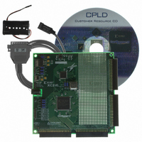
Manufacturer Part Number
DO-CPLD-DK-G
Description
KIT DESIGN CPLD W/BATT HOLDER
Manufacturer
Xilinx Inc
Series
CoolRunner™- IIr
Type
CPLDr
Specifications of DO-CPLD-DK-G
Contents
Proto Board, Download Cable, Samples, Software
For Use With/related Products
CoolRunner-ll, XC9500XL
Lead Free Status / RoHS Status
Lead free / RoHS Compliant
Other names
122-1512
Available stocks
Company
Part Number
Manufacturer
Quantity
Price


Xilinx Design Software
Design Tools
Schematic Capture Process
Programmable Logic Design
June 12, 2006
R
Programmable logic design has entered an era in which device densities are measured in
the millions of gates, and system performance is measured in hundreds of megahertz.
Given these system complexities, the critical success factor in the creation of a design is
your productivity.
Xilinx offers complete electronic design tools that enable the implementation of designs in
Xilinx PLDs. These development solutions combine powerful technology with a flexible,
easy-to-use graphical interface to help you achieve the best possible designs within your
project schedule – regardless of your experience level.
The availability of products such as WebPACK ISE software has made it much easier to
design with programmable logic. Designs can be described easily and quickly using a
description language such as ABEL, VHDL, Verilog™, or with a schematic capture
package.
Schematic capture is the traditional method that designers have used to specify gate arrays
and programmable logic devices. It is a graphical tool that allows you to specify the exact
gates required and how you want them connected. There are four basic steps to using
schematic capture:
1.
2.
3.
After selecting a specific schematic capture tool and device library, begin building the
circuit by loading the desired gates from the selected library. You can use any
combination of gates that you need. You must choose a specific vendor and device
family library at this time, but you don’t yet have to know what device within that
family you will ultimately use with respect to package and speed.
Connect the gates together using nets or wires. You have complete control and can
connect the gates in any configuration required by your application.
Add and label the input and output buffers. These will define the I/O package pins for
the device.
www.xilinx.com
Chapter 3
37
Related parts for DO-CPLD-DK-G
Image
Part Number
Description
Manufacturer
Datasheet
Request
R

Part Number:
Description:
STARTER KIT CPLD
Manufacturer:
Xilinx Inc
Datasheet:
Part Number:
Description:
KIT STARTER CPLD JAPANESE
Manufacturer:
Xilinx Inc
Datasheet:
Part Number:
Description:
KIT STARTER CPLD-JAPANESE
Manufacturer:
Xilinx Inc
Datasheet:

Part Number:
Description:
IC CPLD .8K 36MCELL 44-VQFP
Manufacturer:
Xilinx Inc
Datasheet:

Part Number:
Description:
IC CPLD 72MCRCELL 10NS 44VQFP
Manufacturer:
Xilinx Inc
Datasheet:

Part Number:
Description:
IC CPLD 1.6K 72MCELL 64-VQFP
Manufacturer:
Xilinx Inc
Datasheet:

Part Number:
Description:
IC CR-II CPLD 64MCELL 44-VQFP
Manufacturer:
Xilinx Inc
Datasheet:

Part Number:
Description:
IC CPLD 1.6K 72MCELL 100-TQFP
Manufacturer:
Xilinx Inc
Datasheet:

Part Number:
Description:
IC CR-II CPLD 64MCELL 56-BGA
Manufacturer:
Xilinx Inc
Datasheet:

Part Number:
Description:
IC CPLD 72MCRCELL 7.5NS 44VQFP
Manufacturer:
Xilinx Inc
Datasheet:
Part Number:
Description:
IC CR-II CPLD 64MCELL 100-VQFP
Manufacturer:
Xilinx Inc
Datasheet:
Part Number:
Description:
IC CPLD 1.6K 72MCELL 100-TQFP
Manufacturer:
Xilinx Inc
Datasheet:

Part Number:
Description:
IC CPLD 72MCRCELL 7.5NS 64VQFP
Manufacturer:
Xilinx Inc
Datasheet:
Part Number:
Description:
IC CPLD 1.6K 72MCELL 100-TQFP
Manufacturer:
Xilinx Inc
Datasheet:

Part Number:
Description:
IC CPLD 1.5K 64MCELL HP 44-VQFP
Manufacturer:
Xilinx Inc