DSP56309EVM Freescale Semiconductor, DSP56309EVM Datasheet - Page 119
DSP56309EVM
Manufacturer Part Number
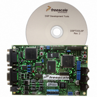
DSP56309EVM
Description
KIT EVALUATION FOR XC56309
Manufacturer
Freescale Semiconductor
Type
DSPr
Specifications of DSP56309EVM
Contents
Module Board, Installation Guide, Power Supply, Cable, Software and more
Description/function
Audio DSPs
Product
Audio Modules
For Use With/related Products
DSP56309
Lead Free Status / RoHS Status
Contains lead / RoHS non-compliant


6.6.7 Host Transmit (HTX) Register
The HTX register is used in DSP-to-host data transfers. The DSP56309 views it as a 24-bit
write-only register. Its address is X:$FFFFC7. Writing to the HTX register clears the host transfer
data empty bit (HSR[HTDE]) on the DSP side. The contents of the HTX register are transferred
as 24-bit data to the Receive Data Registers (RXH:RXM:RXL) when both HSR[HTDE] and
receive data full (ISR[RXDF]) on the host-side bits are cleared. This transfer operation sets the
ISR[RXDF] and HSR[HTDE] bits. The DSP56309 can set the HCR[HTIE] bit to cause a host
transmit data interrupt when HSR[HTDE] is set. To prevent the previous data from being
overwritten, the DSP56309 should never write to the HTX when HSR[HTDE] is cleared.
Note:
6.6.8 Host Receive (HRX) Register
The HRX register is used in host-to-DSP data transfers. The DSP56309 views it as a 24-bit
read-only register. Its address is X:$FFFFC6. It is loaded with 24-bit data from the transmit data
Freescale Semiconductor
In a single-strobe mode, a DS (data strobe) signal qualifies the access, while a R/W (Read-Write)
signal specifies the direction of the access.
HRW
HDS
HWR
HRD
Data
Data
In dual-strobe mode, separate HRD and HWR signals specify the access as a read or write
access, respectively.
When data is written to a peripheral device, there is a two-cycle pipeline delay until
any status bits affected by this operation are updated. If you read any of the status bits
within the next two cycles, the bit does not reflect its current status. For details, see
Section 6.4.1, Software Polling, on page 6-6.
Write Cycle
Read Cycle
Figure 6-13. Single-Strobe Mode
Figure 6-14. Dual-Strobe Mode
DSP56309 User’s Manual, Rev. 1
Write Data In
Read Data Out
DSP Core Programming Model
6-19
Related parts for DSP56309EVM
Image
Part Number
Description
Manufacturer
Datasheet
Request
R

Part Number:
Description:
Manufacturer:
Freescale Semiconductor, Inc
Datasheet:
Part Number:
Description:
Manufacturer:
Freescale Semiconductor, Inc
Datasheet:
Part Number:
Description:
Manufacturer:
Freescale Semiconductor, Inc
Datasheet:
Part Number:
Description:
Manufacturer:
Freescale Semiconductor, Inc
Datasheet:
Part Number:
Description:
Manufacturer:
Freescale Semiconductor, Inc
Datasheet:
Part Number:
Description:
Manufacturer:
Freescale Semiconductor, Inc
Datasheet:
Part Number:
Description:
Manufacturer:
Freescale Semiconductor, Inc
Datasheet:
Part Number:
Description:
Manufacturer:
Freescale Semiconductor, Inc
Datasheet:
Part Number:
Description:
Manufacturer:
Freescale Semiconductor, Inc
Datasheet:
Part Number:
Description:
Manufacturer:
Freescale Semiconductor, Inc
Datasheet:
Part Number:
Description:
Manufacturer:
Freescale Semiconductor, Inc
Datasheet:
Part Number:
Description:
Manufacturer:
Freescale Semiconductor, Inc
Datasheet:
Part Number:
Description:
Manufacturer:
Freescale Semiconductor, Inc
Datasheet:
Part Number:
Description:
Manufacturer:
Freescale Semiconductor, Inc
Datasheet:
Part Number:
Description:
Manufacturer:
Freescale Semiconductor, Inc
Datasheet: