DSP56309EVM Freescale Semiconductor, DSP56309EVM Datasheet - Page 199
DSP56309EVM
Manufacturer Part Number
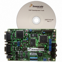
DSP56309EVM
Description
KIT EVALUATION FOR XC56309
Manufacturer
Freescale Semiconductor
Type
DSPr
Specifications of DSP56309EVM
Contents
Module Board, Installation Guide, Power Supply, Cable, Software and more
Description/function
Audio DSPs
Product
Audio Modules
For Use With/related Products
DSP56309
Lead Free Status / RoHS Status
Contains lead / RoHS non-compliant


9.3.1.2 Timer Pulse (Mode 1)
In Mode 1, the timer generates an external pulse on its TIO signal when the timer count reaches a
pre-set value. The TIO signal is loaded with the value of the TCSR[INV] bit. When the counter
matches the TCPR value, TCSR[TCF] is set and a compare interrupt is generated if the
TCSR[TCIE] bit is set. The polarity of the TIO signal is inverted for one timer clock period. If
TCSR[TRM] is set, the counter is loaded with the TLR value on the next timer clock and the
count is resumed. If TCSR[TRM] is cleared, the counter continues to increment on each timer
clock. This process repeats until TCSR[TE] is cleared (disabling the timer).
The TLR value in the TCPR sets the delay between starting the timer and generating the output
pulse. To generate successive output pulses with a delay of X clock cycles between signals, set
the TLR value to X/2 and set the TCSR[TRM] bit. This process repeats until the timer is
disabled.
Freescale Semiconductor
TC3
0
Mode 1 (internal clock): TRM = 1
N = write preload
M = write compare
TC2
Bit Settings
0
TE
Clock
(CLK/2 or prescale CLK)
TLR
Counter (TCR)
TCPR
TCF (Compare Interrupt if TCIE = 1)
TIO pin (INV = 0)
TIO pin (INV = 1)
TC1
0
TC0
1
N
M
Figure 9-5. Pulse Mode (TRM = 1)
0
Mode
DSP56309 User’s Manual, Rev. 1
1
first event
N
Timer Pulse
Name
N + 1
Mode Characteristics
M
Function
Timer
N
pulse width =
timer clock
period
Output
TIO
N + 1
Operating Modes
Internal
Clock
9-7
Related parts for DSP56309EVM
Image
Part Number
Description
Manufacturer
Datasheet
Request
R

Part Number:
Description:
Manufacturer:
Freescale Semiconductor, Inc
Datasheet:
Part Number:
Description:
Manufacturer:
Freescale Semiconductor, Inc
Datasheet:
Part Number:
Description:
Manufacturer:
Freescale Semiconductor, Inc
Datasheet:
Part Number:
Description:
Manufacturer:
Freescale Semiconductor, Inc
Datasheet:
Part Number:
Description:
Manufacturer:
Freescale Semiconductor, Inc
Datasheet:
Part Number:
Description:
Manufacturer:
Freescale Semiconductor, Inc
Datasheet:
Part Number:
Description:
Manufacturer:
Freescale Semiconductor, Inc
Datasheet:
Part Number:
Description:
Manufacturer:
Freescale Semiconductor, Inc
Datasheet:
Part Number:
Description:
Manufacturer:
Freescale Semiconductor, Inc
Datasheet:
Part Number:
Description:
Manufacturer:
Freescale Semiconductor, Inc
Datasheet:
Part Number:
Description:
Manufacturer:
Freescale Semiconductor, Inc
Datasheet:
Part Number:
Description:
Manufacturer:
Freescale Semiconductor, Inc
Datasheet:
Part Number:
Description:
Manufacturer:
Freescale Semiconductor, Inc
Datasheet:
Part Number:
Description:
Manufacturer:
Freescale Semiconductor, Inc
Datasheet:
Part Number:
Description:
Manufacturer:
Freescale Semiconductor, Inc
Datasheet: