DSP56309EVM Freescale Semiconductor, DSP56309EVM Datasheet - Page 216
DSP56309EVM
Manufacturer Part Number
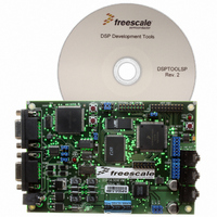
DSP56309EVM
Description
KIT EVALUATION FOR XC56309
Manufacturer
Freescale Semiconductor
Type
DSPr
Specifications of DSP56309EVM
Contents
Module Board, Installation Guide, Power Supply, Cable, Software and more
Description/function
Audio DSPs
Product
Audio Modules
For Use With/related Products
DSP56309
Lead Free Status / RoHS Status
Contains lead / RoHS non-compliant


Triple Timer Module
9.4.4 Timer Control/Status Register (TCSR)
The TCSR is a read/write register controlling the timer and reflecting its status.
9-24
Bit Number
DIR
23
11
23–22
19–16
21
20
15
14
Reserved. Read as 0. Write to 0 for future compatibility
22
10
Bit Name
Table 9-3. Timer Control/Status Register (TCSR) Bit Definitions
TOF
PCE
TCF
TRM
TCF
21
9
Figure 9-23. Timer Control/Status Register (TCSR)
TOF
INV
Reset Value
20
8
0
0
0
0
0
0
TC3
19
7
DSP56309 User’s Manual, Rev. 1
Reserved. Write to zero for future compatibility.
Timer Compare Flag
Indicate that the event count is complete. In timer, PWM, and watchdog
modes, the TCF bit is set after (M – N + 1) events are counted. (M is the
value in the compare register and N is the TLR value.) In measurement
modes, the TCF bit is set when the measurement completes. Writing a one to
the TCF bit clears it. A zero written to the TCF bit has no effect. The bit is also
cleared when the timer compare interrupt is serviced. The TCF bit is cleared
by a hardware RESET signal, a software RESET instruction, the STOP
instruction, or by clearing the TCSR[TE] bit to disable the timer.
Note:
Timer Overflow Flag
Indicates that a counter overflow has occurred. This bit is cleared by writing a
one to the TOF bit. Writing a zero to TOF has no effect. The bit is also cleared
when the timer overflow interrupt is serviced. The TOF bit is cleared by a
hardware RESET signal, a software RESET instruction, the STOP
instruction, or by clearing the TCSR[TE] bit to disable the timer
Reserved. Write to zero for future compatibility.
Prescaler Clock Enable
Selects the prescaler clock as the timer source clock. When PCE is cleared,
the timer uses either an internal (CLK/2) signal or an external (TIO) signal as
its source clock. When PCE is set, the prescaler output is the timer source
clock for the counter, regardless of the timer operating mode. To ensure
proper operation, the PCE bit is changed only when the timer is disabled. The
PS[1–0] bits of the TPLR determine which source clock is used for the
prescaler. A timer can be clocked by a prescaler clock that is derived from the
TIO of another timer.
Reserved. Write to zero for future compatibility.
TC2
18
6
The TOF and TCF bits are cleared by a 1 written to the specific bit.
To ensure that only the target bit is cleared, do not use the BSET
command. The proper way to clear these bits is to write 1, using a
MOVEP instruction, to the flag to be cleared and 0 to the other flag.
TC1
17
5
TC0
16
4
Description
PCE
15
3
TCIE
14
2
TOIE
Freescale Semiconductor
DO
13
1
.
TE
12
DI
0
Related parts for DSP56309EVM
Image
Part Number
Description
Manufacturer
Datasheet
Request
R

Part Number:
Description:
Manufacturer:
Freescale Semiconductor, Inc
Datasheet:
Part Number:
Description:
Manufacturer:
Freescale Semiconductor, Inc
Datasheet:
Part Number:
Description:
Manufacturer:
Freescale Semiconductor, Inc
Datasheet:
Part Number:
Description:
Manufacturer:
Freescale Semiconductor, Inc
Datasheet:
Part Number:
Description:
Manufacturer:
Freescale Semiconductor, Inc
Datasheet:
Part Number:
Description:
Manufacturer:
Freescale Semiconductor, Inc
Datasheet:
Part Number:
Description:
Manufacturer:
Freescale Semiconductor, Inc
Datasheet:
Part Number:
Description:
Manufacturer:
Freescale Semiconductor, Inc
Datasheet:
Part Number:
Description:
Manufacturer:
Freescale Semiconductor, Inc
Datasheet:
Part Number:
Description:
Manufacturer:
Freescale Semiconductor, Inc
Datasheet:
Part Number:
Description:
Manufacturer:
Freescale Semiconductor, Inc
Datasheet:
Part Number:
Description:
Manufacturer:
Freescale Semiconductor, Inc
Datasheet:
Part Number:
Description:
Manufacturer:
Freescale Semiconductor, Inc
Datasheet:
Part Number:
Description:
Manufacturer:
Freescale Semiconductor, Inc
Datasheet:
Part Number:
Description:
Manufacturer:
Freescale Semiconductor, Inc
Datasheet: