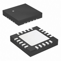
Z8F1233QH020SG Zilog, Z8F1233QH020SG Datasheet - Page 66

Z8F1233QH020SG
Manufacturer Part Number
Z8F1233QH020SG
Description
IC ENCORE XP MCU FLSH 12K 20QFN
Manufacturer
Zilog
Series
Encore!®r
Specifications of Z8F1233QH020SG
Core Processor
Z8
Core Size
8-Bit
Speed
20MHz
Peripherals
Brown-out Detect/Reset, LED, POR, PWM, WDT
Number Of I /o
17
Program Memory Size
12KB (12K x 8)
Program Memory Type
FLASH
Ram Size
256 x 8
Voltage - Supply (vcc/vdd)
2.7 V ~ 3.6 V
Oscillator Type
Internal
Operating Temperature
0°C ~ 70°C
Package / Case
20-VQFN Exposed Pad, 20-HVQFN, 20-SQFN, 20-DHVQFN
For Use With
770-1002 - ISP 4PORT ZILOG Z8 ENCORE! MCU
Lead Free Status / RoHS Status
Lead free / RoHS Compliant
Eeprom Size
-
Data Converters
-
Connectivity
-
Other names
269-4656
Available stocks
Company
Part Number
Manufacturer
Quantity
Price
Company:
Part Number:
Z8F1233QH020SG
Manufacturer:
Zilog
Quantity:
670
- Current page: 66 of 251
- Download datasheet (4Mb)
PS025111-1207
Caution:
Interrupt Vectors and Priority
Interrupt Assertion
•
•
Interrupts are globally disabled by any of the following actions:
•
•
•
•
•
•
•
•
The interrupt controller supports three levels of interrupt priority. Level 3 is the highest
priority, level 2 is the second highest priority, and level 1 is the lowest priority. If all the
interrupts are enabled with identical interrupt priority (all as level 2 interrupts, for
example), the interrupt priority is assigned from highest to lowest as specified in
on page 54. Level 3 interrupts are always assigned higher priority than level 2 interrupts
and level 2 interrupts are assigned higher priority than level 1 interrupts. Within each
interrupt priority level (level 1, level 2, or level 3), priority is assigned as specified in
Table
Watchdog Oscillator fail trap, and illegal instruction trap always have highest (level 3)
priority.
Interrupt sources assert their interrupt requests for only a single system clock period
(single pulse). When the interrupt request is acknowledged by the eZ8 CPU, the
corresponding bit in the interrupt request register is cleared. Writing 0 to the
corresponding bit in the interrupt request register clears the interrupt request.
The coding style listed below that clears the bits in the interrupt request registers is not
recommended. All incoming interrupts received between execution of the first LDX
command and the final LDX command are lost.
Execution of an IRET (return from interrupt) instruction
Writing 1 to the IRQE bit in the interrupt control register
Execution of a
eZ8 CPU acknowledgement of an interrupt service request from the interrupt controller
Writing a 0 to the IRQE bit in the interrupt control register
Reset
Execution of a trap instruction
Illegal instruction Trap
Primary oscillator fail trap
Watchdog Oscillator fail trap
31, above. Reset, Watchdog Timer interrupt (if enabled), primary oscillator fail trap,
Poor coding style that can result in lost interrupt requests:
LDX r0, IRQ0
DI
(disable interrupt) instruction
Z8 Encore!
Product Specification
®
Interrupt Controller
F0830 Series
Table 31
56
Related parts for Z8F1233QH020SG
Image
Part Number
Description
Manufacturer
Datasheet
Request
R

Part Number:
Description:
Communication Controllers, ZILOG INTELLIGENT PERIPHERAL CONTROLLER (ZIP)
Manufacturer:
Zilog, Inc.
Datasheet:

Part Number:
Description:
KIT DEV FOR Z8 ENCORE 16K TO 64K
Manufacturer:
Zilog
Datasheet:

Part Number:
Description:
KIT DEV Z8 ENCORE XP 28-PIN
Manufacturer:
Zilog
Datasheet:

Part Number:
Description:
DEV KIT FOR Z8 ENCORE 8K/4K
Manufacturer:
Zilog
Datasheet:

Part Number:
Description:
KIT DEV Z8 ENCORE XP 28-PIN
Manufacturer:
Zilog
Datasheet:

Part Number:
Description:
DEV KIT FOR Z8 ENCORE 4K TO 8K
Manufacturer:
Zilog
Datasheet:

Part Number:
Description:
CMOS Z8 microcontroller. ROM 16 Kbytes, RAM 256 bytes, speed 16 MHz, 32 lines I/O, 3.0V to 5.5V
Manufacturer:
Zilog, Inc.
Datasheet:

Part Number:
Description:
Low-cost microcontroller. 512 bytes ROM, 61 bytes RAM, 8 MHz
Manufacturer:
Zilog, Inc.
Datasheet:

Part Number:
Description:
Z8 4K OTP Microcontroller
Manufacturer:
Zilog, Inc.
Datasheet:

Part Number:
Description:
CMOS SUPER8 ROMLESS MCU
Manufacturer:
Zilog, Inc.
Datasheet:

Part Number:
Description:
SL1866 CMOSZ8 OTP Microcontroller
Manufacturer:
Zilog, Inc.
Datasheet:

Part Number:
Description:
SL1866 CMOSZ8 OTP Microcontroller
Manufacturer:
Zilog, Inc.
Datasheet:

Part Number:
Description:
OTP (KB) = 1, RAM = 125, Speed = 12, I/O = 14, 8-bit Timers = 2, Comm Interfaces Other Features = Por, LV Protect, Voltage = 4.5-5.5V
Manufacturer:
Zilog, Inc.
Datasheet:

Part Number:
Description:
Manufacturer:
Zilog, Inc.
Datasheet:


