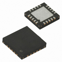
ATTINY4313-MU Atmel, ATTINY4313-MU Datasheet - Page 30

ATTINY4313-MU
Manufacturer Part Number
ATTINY4313-MU
Description
IC MCU AVR 4K FLASH 20QFN
Manufacturer
Atmel
Series
AVR® ATtinyr
Specifications of ATTINY4313-MU
Core Processor
AVR
Core Size
8-Bit
Speed
20MHz
Connectivity
I²C, SPI, UART/USART
Peripherals
Brown-out Detect/Reset, POR, PWM, WDT
Number Of I /o
18
Program Memory Size
4KB (2K x 16)
Program Memory Type
FLASH
Eeprom Size
256 x 8
Ram Size
256 x 8
Voltage - Supply (vcc/vdd)
1.8 V ~ 5.5 V
Oscillator Type
Internal
Operating Temperature
-40°C ~ 85°C
Package / Case
20-VQFN Exposed Pad, 20-HVQFN, 20-SQFN, 20-DHVQFN
Processor Series
ATtiny
Core
AVR
Data Bus Width
8 bit
Data Ram Size
256 B
Interface Type
SPI, USART, USI
Maximum Clock Frequency
20 MHz
Number Of Programmable I/os
18
Number Of Timers
2
Operating Supply Voltage
3.3 V
Maximum Operating Temperature
+ 85 C
Mounting Style
SMD/SMT
Minimum Operating Temperature
- 40 C
Operating Temperature Range
- 40 C to + 85 C
Lead Free Status / RoHS Status
Lead free / RoHS Compliant
Data Converters
-
Lead Free Status / Rohs Status
Details
Available stocks
Company
Part Number
Manufacturer
Quantity
Price
Company:
Part Number:
ATTINY4313-MU
Manufacturer:
HITTITE
Quantity:
101
- Current page: 30 of 270
- Download datasheet (7Mb)
6.4
6.5
6.5.1
6.5.2
30
Clock Output Buffer
Register Description
ATtiny2313A/4313
OSCCAL – Oscillator Calibration Register
CLKPR – Clock Prescale Register
The device can output the system clock on the CLKO pin. To enable the output, the CKOUT
fuse has to be programmed. This mode is suitable when the chip clock is used to drive other cir-
cuits on the system. Note that the clock will not be output during reset and that the normal
operation of the I/O pin will be overridden when the fuse is programmed. Any clock source,
including the internal RC Oscillator, can be selected when the clock is output on CLKO. If the
System Clock Prescaler is used, it is the divided system clock that is output.
• Bit 7 – Res: Reserved Bit
This bit is reserved bit in ATtiny2313A/4313 and it will always read zero.
• Bits 6:0 – CAL[6:0]: Oscillator Calibration Value
Writing the calibration byte to this address will trim the internal Oscillator to remove process vari-
ations from the Oscillator frequency. This is done automatically during Chip Reset. When
OSCCAL is zero, the lowest available frequency is chosen. Writing non-zero values to this regis-
ter will increase the frequency of the internal Oscillator. Writing 0x7F to the register gives the
highest available frequency.
The calibrated Oscillator is used to time EEPROM and Flash access. If EEPROM or Flash is
written, do not calibrate to more than 10% above the nominal frequency. Otherwise, the
EEPROM or Flash write may fail. Note that the Oscillator is intended for calibration to 8 MHz or 4
MHz. Tuning to other values is not guaranteed, as indicated in
To ensure stable operation of the MCU the calibration value should be changed in small steps. A
variation in frequency of more than 2% from one cycle to the next can lead to unpredicatble
behavior. Changes in OSCCAL should not exceed 0x20 for each calibration. It is required to
ensure that the MCU is kept in Reset during such changes in the clock frequency
Table 6-8.
• Bit 7 – CLKPCE: Clock Prescaler Change Enable
Bit
0x31 (0x51)
Read/Write
Initial Value
Bit
0x26 (0x46)
Read/Write
Initial Value
OSCCAL Value
0x3F
0x7F
0x00
Internal RC Oscillator Frequency Range
CLKPCE
R/W
R
7
–
0
7
0
with Respect to Nominal Frequency
CAL6
R/W
Typical Lowest Frequency
6
R
6
–
0
CAL5
R/W
5
100%
R
5
–
0
50%
75%
Device Specific Calibration Value
CAL4
R/W
4
R
4
–
0
CLKPS3
CAL3
R/W
R/W
3
3
with Respect to Nominal Frequency
CLKPS2
See Bit Description
CAL2
R/W
R/W
2
2
Table 6-8
Typical Highest Frequency
CLKPS1
CAL1
R/W
R/W
1
1
below.
100%
150%
200%
CLKPS0
CAL0
R/W
R/W
0
0
8246A–AVR–11/09
OSCCAL
CLKPR
Related parts for ATTINY4313-MU
Image
Part Number
Description
Manufacturer
Datasheet
Request
R

Part Number:
Description:
Manufacturer:
Atmel Corporation
Datasheet:

Part Number:
Description:
Microcontrollers (MCU) 512B FL 32B SRAM TIMER ATTINY4 12MHz
Manufacturer:
Atmel

Part Number:
Description:
IC MCU AVR 512B FLASH SOT-23-6
Manufacturer:
Atmel
Datasheet:

Part Number:
Description:
IC MCU AVR 512B FLASH SOT-23-6
Manufacturer:
Atmel
Datasheet:

Part Number:
Description:
DEV KIT FOR AVR/AVR32
Manufacturer:
Atmel
Datasheet:

Part Number:
Description:
INTERVAL AND WIPE/WASH WIPER CONTROL IC WITH DELAY
Manufacturer:
ATMEL Corporation
Datasheet:

Part Number:
Description:
Low-Voltage Voice-Switched IC for Hands-Free Operation
Manufacturer:
ATMEL Corporation
Datasheet:

Part Number:
Description:
MONOLITHIC INTEGRATED FEATUREPHONE CIRCUIT
Manufacturer:
ATMEL Corporation
Datasheet:

Part Number:
Description:
AM-FM Receiver IC U4255BM-M
Manufacturer:
ATMEL Corporation
Datasheet:

Part Number:
Description:
Monolithic Integrated Feature Phone Circuit
Manufacturer:
ATMEL Corporation
Datasheet:

Part Number:
Description:
Multistandard Video-IF and Quasi Parallel Sound Processing
Manufacturer:
ATMEL Corporation
Datasheet:


