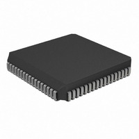
PIC17LC756A-08/L Microchip Technology, PIC17LC756A-08/L Datasheet - Page 293

PIC17LC756A-08/L
Manufacturer Part Number
PIC17LC756A-08/L
Description
IC MCU OTP 16KX16 A/D 68PLCC
Manufacturer
Microchip Technology
Series
PIC® 17Cr
Specifications of PIC17LC756A-08/L
Core Processor
PIC
Core Size
8-Bit
Speed
8MHz
Connectivity
I²C, SPI, UART/USART
Peripherals
Brown-out Detect/Reset, POR, PWM, WDT
Number Of I /o
50
Program Memory Size
32KB (16K x 16)
Program Memory Type
OTP
Ram Size
902 x 8
Voltage - Supply (vcc/vdd)
3 V ~ 5.5 V
Data Converters
A/D 12x10b
Oscillator Type
External
Operating Temperature
0°C ~ 70°C
Package / Case
68-PLCC
Processor Series
PIC17LC
Core
PIC
Data Bus Width
8 bit
Data Ram Size
902 B
Interface Type
I2C, MSSP, RS- 232, SCI, SPI, USART
Maximum Clock Frequency
8 MHz
Number Of Programmable I/os
50
Number Of Timers
8
Operating Supply Voltage
3 V to 5.5 V
Maximum Operating Temperature
+ 70 C
Mounting Style
SMD/SMT
Minimum Operating Temperature
0 C
On-chip Adc
12 bit
Lead Free Status / RoHS Status
Lead free / RoHS Compliant
Eeprom Size
-
Lead Free Status / Rohs Status
Details
Available stocks
Company
Part Number
Manufacturer
Quantity
Price
Company:
Part Number:
PIC17LC756A-08/L
Manufacturer:
MICROCHIP
Quantity:
12 000
Company:
Part Number:
PIC17LC756A-08/L
Manufacturer:
Microchip Technology
Quantity:
10 000
MOVPF ....................................................................... 46, 218
MOVWF ............................................................................ 218
MPLAB Integrated Development Environment Software .. 233
MULLW ............................................................................. 219
Multi-Master Communication ............................................ 170
Multi-Master Mode ............................................................ 152
Multiply Examples
MULWF ............................................................................. 219
N
NEGW ............................................................................... 220
NOP .................................................................................. 220
O
Opcode Field Descriptions ................................................ 197
Opcodes.............................................................................. 56
Oscillator
Oscillator Start-up Time (Figure)......................................... 24
Oscillator Start-up Timer (OST) .......................................... 24
OST..................................................................................... 24
OV ................................................................................. 11, 51
Overflow (OV) ..................................................................... 11
P
P........................................................................................ 134
Packaging Information ...................................................... 281
PC (Program Counter) ........................................................ 56
PCFG0 bit ......................................................................... 180
PCFG1 bit ......................................................................... 180
PCFG2 bit ......................................................................... 180
PCH .................................................................................... 56
PCL ............................................................................. 56, 198
PCLATH .............................................................................. 56
PD ............................................................................... 52, 194
PEIE ............................................................................ 34, 111
PEIF .................................................................................... 34
Peripheral Bank .................................................................. 57
Peripheral Banks................................................................. 57
Peripheral Interrupt Enable ................................................. 35
Peripheral Interrupt Request (PIR1) ................................... 37
Peripheral Register Banks .................................................. 46
PICDEM-1 Low-Cost PICmicro Demo Board.................... 235
PICDEM-2 Low-Cost PIC16CXX Demo Board ................. 235
PICDEM-3 Low-Cost PIC16CXXX Demo Board............... 236
PICSTART“ Plus Entry Level Development System ......... 235
PIE .................................................................... 126, 130, 132
PIE1 .............................................................................. 28, 48
PIE2 ........................................................................ 28, 36, 49
PIR .................................................................... 126, 130, 132
PIR1 .............................................................................. 28, 48
PIR2 .............................................................................. 28, 49
PM0........................................................................... 191, 195
PM1........................................................................... 191, 195
POP .............................................................................. 39, 54
POR .................................................................................... 24
PORTA.................................................................... 27, 48, 72
2000 Microchip Technology Inc.
16 x 16 Routine........................................................... 68
16 x 16 Signed Routine............................................... 69
8 x 8 Routine............................................................... 67
8 x 8 Signed Routine................................................... 67
Configuration....................................................... 17, 192
Crystal......................................................................... 17
External Clock............................................................. 19
External Crystal Circuit ............................................... 19
External Parallel Resonant Crystal Circuit .................. 19
External Series Resonant Crystal Circuit.................... 19
RC............................................................................... 20
RC Frequencies ........................................................ 269
PORTB ................................................................... 27, 48, 74
PORTB Interrupt on Change .............................................. 37
PORTC ................................................................... 28, 48, 78
PORTD ................................................................... 28, 48, 80
PORTE ................................................................... 28, 48, 82
PORTF ............................................................................... 49
PORTG ............................................................................... 49
Power-down Mode............................................................ 194
Power-on Reset (POR)....................................................... 24
Power-up Timer (PWRT) .................................................... 24
PR1............................................................................... 28, 49
PR2............................................................................... 28, 49
PR3/CA1H .......................................................................... 28
PR3/CA1L........................................................................... 28
PR3H/CA1H........................................................................ 49
PR3L/CA1L......................................................................... 49
Prescaler Assignments ....................................................... 99
PRO MATE“ II Universal Programmer.............................. 235
PRODH......................................................................... 30, 50
PRODL ......................................................................... 30, 50
Program Counter (PC)........................................................ 56
Program Memory
Protected Microcontroller.................................................... 43
PS0 ............................................................................... 53, 97
PS1 ............................................................................... 53, 97
PS2 ............................................................................... 53, 97
PS3 ............................................................................... 53, 97
PUSH............................................................................ 39, 54
PW1DCH ...................................................................... 28, 49
PW1DCL....................................................................... 28, 49
PW2DCH ...................................................................... 28, 49
PW2DCL....................................................................... 28, 49
PW3DCH ...................................................................... 30, 50
PW3DCL....................................................................... 30, 50
PWM ......................................................................... 101, 107
PWM1 ....................................................................... 102, 103
PWM1ON.................................................................. 102, 107
PWM2 ....................................................................... 102, 103
PWM2ON.................................................................. 102, 107
PWM3ON.......................................................................... 103
PWRT ................................................................................. 24
External Access Waveforms....................................... 45
External Connection Diagram..................................... 45
Map............................................................................. 43
Modes
Operation.................................................................... 43
Organization ............................................................... 43
Duty Cycle ................................................................ 108
External Clock Source .............................................. 109
Frequency vs. Resolution ......................................... 108
Interrupts .................................................................. 108
Max Resolution/Frequency for External Clock Input 109
Output....................................................................... 107
Periods ..................................................................... 108
Extended Microcontroller.................................... 43
Microcontroller .................................................... 43
Microprocessor ................................................... 43
Protected Microcontroller.................................... 43
PIC17C7XX
DS30289B-page 293


