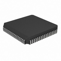
PIC17LC756A-08/L Microchip Technology, PIC17LC756A-08/L Datasheet - Page 37

PIC17LC756A-08/L
Manufacturer Part Number
PIC17LC756A-08/L
Description
IC MCU OTP 16KX16 A/D 68PLCC
Manufacturer
Microchip Technology
Series
PIC® 17Cr
Specifications of PIC17LC756A-08/L
Core Processor
PIC
Core Size
8-Bit
Speed
8MHz
Connectivity
I²C, SPI, UART/USART
Peripherals
Brown-out Detect/Reset, POR, PWM, WDT
Number Of I /o
50
Program Memory Size
32KB (16K x 16)
Program Memory Type
OTP
Ram Size
902 x 8
Voltage - Supply (vcc/vdd)
3 V ~ 5.5 V
Data Converters
A/D 12x10b
Oscillator Type
External
Operating Temperature
0°C ~ 70°C
Package / Case
68-PLCC
Processor Series
PIC17LC
Core
PIC
Data Bus Width
8 bit
Data Ram Size
902 B
Interface Type
I2C, MSSP, RS- 232, SCI, SPI, USART
Maximum Clock Frequency
8 MHz
Number Of Programmable I/os
50
Number Of Timers
8
Operating Supply Voltage
3 V to 5.5 V
Maximum Operating Temperature
+ 70 C
Mounting Style
SMD/SMT
Minimum Operating Temperature
0 C
On-chip Adc
12 bit
Lead Free Status / RoHS Status
Lead free / RoHS Compliant
Eeprom Size
-
Lead Free Status / Rohs Status
Details
Available stocks
Company
Part Number
Manufacturer
Quantity
Price
Company:
Part Number:
PIC17LC756A-08/L
Manufacturer:
MICROCHIP
Quantity:
12 000
Company:
Part Number:
PIC17LC756A-08/L
Manufacturer:
Microchip Technology
Quantity:
10 000
- Current page: 37 of 304
- Download datasheet (6Mb)
6.3
These registers contains the individual flag bits for the
peripheral interrupts.
REGISTER 6-4: PIR1 REGISTER (ADDRESS: 16h, BANK 1)
2000 Microchip Technology Inc.
bit 7
bit 6
bit 5
bit 4
bit 3
bit 2
bit 1
bit 0
Peripheral Interrupt Request
Register1 (PIR1) and Register2
(PIR2)
Legend:
R = Readable bit
- n = Value at POR Reset
bit 7
RBIF: PORTB Interrupt-on-Change Flag bit
1 = One of the PORTB inputs changed (software must end the mismatch condition)
0 = None of the PORTB inputs have changed
TMR3IF: TMR3 Interrupt Flag bit
If Capture1 is enabled (CA1/PR3 = 1):
1 = TMR3 overflowed
0 = TMR3 did not overflow
If Capture1 is disabled (CA1/PR3 = 0):
1 = TMR3 value has rolled over to 0000h from equalling the period register (PR3H:PR3L) value
0 = TMR3 value has not rolled over to 0000h from equalling the period register (PR3H:PR3L)
TMR2IF: TMR2 Interrupt Flag bit
1 = TMR2 value has rolled over to 0000h from equalling the period register (PR2) value
0 = TMR2 value has not rolled over to 0000h from equalling the period register (PR2) value
TMR1IF: TMR1 Interrupt Flag bit
If TMR1 is in 8-bit mode (T16 = 0):
1 = TMR1 value has rolled over to 0000h from equalling the period register (PR1) value
0 = TMR1 value has not rolled over to 0000h from equalling the period register (PR1) value
If Timer1 is in 16-bit mode (T16 = 1):
1 = TMR2:TMR1 value has rolled over to 0000h from equalling the period register (PR2:PR1)
0 = TMR2:TMR1 value has not rolled over to 0000h from equalling the period register (PR2:PR1)
CA2IF: Capture2 Interrupt Flag bit
1 = Capture event occurred on RB1/CAP2 pin
0 = Capture event did not occur on RB1/CAP2 pin
CA1IF: Capture1 Interrupt Flag bit
1 = Capture event occurred on RB0/CAP1 pin
0 = Capture event did not occur on RB0/CAP1 pin
TX1IF: USART1 Transmit Interrupt Flag bit (state controlled by hardware)
1 = USART1 Transmit buffer is empty
0 = USART1 Transmit buffer is full
RC1IF: USART1 Receive Interrupt Flag bit (state controlled by hardware)
1 = USART1 Receive buffer is full
0 = USART1 Receive buffer is empty
R/W-x
RBIF
value
value
value
TMR3IF
R/W-0
TMR2IF
R/W-0
W = Writable bit
’1’ = Bit is set
TMR1IF
R/W-0
Note:
R/W-0
CA2IF
U = Unimplemented bit, read as ‘0’
’0’ = Bit is cleared
These bits will be set by the specified condi-
tion, even if the corresponding interrupt
enable bit is cleared (interrupt disabled), or
the GLINTD bit is set (all interrupts disabled).
Before enabling an interrupt, the user may
wish to clear the interrupt flag to ensure that
the program does not immediately branch to
the peripheral Interrupt Service Routine.
CA1IF
R/W-0
PIC17C7XX
x = Bit is unknown
TX1IF
R-1
DS30289B-page 37
RC1IF
R-0
bit 0
Related parts for PIC17LC756A-08/L
Image
Part Number
Description
Manufacturer
Datasheet
Request
R

Part Number:
Description:
MICRO CTRL 16K LOW PWR 68PLCC
Manufacturer:
Microchip Technology
Datasheet:

Part Number:
Description:
MICRO CTRL 16K LOW PWR 64SDIP
Manufacturer:
Microchip Technology
Datasheet:

Part Number:
Description:
MICRO CTRL 16K LOW PWR 64SDIP
Manufacturer:
Microchip Technology
Datasheet:

Part Number:
Description:
MICRO CTRL 16K LOW PWR 68PLCC
Manufacturer:
Microchip Technology
Datasheet:

Part Number:
Description:
Manufacturer:
Microchip Technology Inc.
Datasheet:

Part Number:
Description:
Manufacturer:
Microchip Technology Inc.
Datasheet:

Part Number:
Description:
Manufacturer:
Microchip Technology Inc.
Datasheet:

Part Number:
Description:
Manufacturer:
Microchip Technology Inc.
Datasheet:

Part Number:
Description:
Manufacturer:
Microchip Technology Inc.
Datasheet:

Part Number:
Description:
Manufacturer:
Microchip Technology Inc.
Datasheet:

Part Number:
Description:
Manufacturer:
Microchip Technology Inc.
Datasheet:


