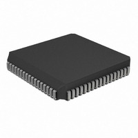
PIC17LC756A-08/L Microchip Technology, PIC17LC756A-08/L Datasheet - Page 296

PIC17LC756A-08/L
Manufacturer Part Number
PIC17LC756A-08/L
Description
IC MCU OTP 16KX16 A/D 68PLCC
Manufacturer
Microchip Technology
Series
PIC® 17Cr
Specifications of PIC17LC756A-08/L
Core Processor
PIC
Core Size
8-Bit
Speed
8MHz
Connectivity
I²C, SPI, UART/USART
Peripherals
Brown-out Detect/Reset, POR, PWM, WDT
Number Of I /o
50
Program Memory Size
32KB (16K x 16)
Program Memory Type
OTP
Ram Size
902 x 8
Voltage - Supply (vcc/vdd)
3 V ~ 5.5 V
Data Converters
A/D 12x10b
Oscillator Type
External
Operating Temperature
0°C ~ 70°C
Package / Case
68-PLCC
Processor Series
PIC17LC
Core
PIC
Data Bus Width
8 bit
Data Ram Size
902 B
Interface Type
I2C, MSSP, RS- 232, SCI, SPI, USART
Maximum Clock Frequency
8 MHz
Number Of Programmable I/os
50
Number Of Timers
8
Operating Supply Voltage
3 V to 5.5 V
Maximum Operating Temperature
+ 70 C
Mounting Style
SMD/SMT
Minimum Operating Temperature
0 C
On-chip Adc
12 bit
Lead Free Status / RoHS Status
Lead free / RoHS Compliant
Eeprom Size
-
Lead Free Status / Rohs Status
Details
Available stocks
Company
Part Number
Manufacturer
Quantity
Price
Company:
Part Number:
PIC17LC756A-08/L
Manufacturer:
MICROCHIP
Quantity:
12 000
Company:
Part Number:
PIC17LC756A-08/L
Manufacturer:
Microchip Technology
Quantity:
10 000
PIC17C7XX
Timer0 ................................................................................. 97
Timer1
Timer2
Timer3
Timers
Timing Diagrams
DS30289B-page 296
16-bit Mode ............................................................... 105
Clock Source Select.................................................. 101
On bit ................................................................ 102, 103
Section .............................................................. 101, 104
Clock Source Select.................................................. 101
On bit ................................................................ 102, 103
Section .............................................................. 101, 110
TCON3 ...................................................................... 103
A/D Conversion ......................................................... 264
Acknowledge Sequence Timing................................ 165
Asynchronous Master Transmission ......................... 123
Asynchronous Reception .......................................... 126
Back to Back Asynchronous Master Transmission ... 124
Baud Rate Generator with Clock Arbitration ............. 153
BRG Reset Due to SDA Collision ............................. 172
Bus Collision
Bus Collision During a RESTART Condition
(Case 1) .................................................................... 173
Bus Collision During a RESTART Condition
(Case 2) .................................................................... 173
Bus Collision During a START Condition
(SCL = 0)................................................................... 172
Bus Collision During a
STOP Condition ........................................................ 174
Bus Collision for Transmit and Acknowledge............ 170
External Parallel Resonant Crystal Oscillator Circuit .. 19
External Program Memory Access ............................. 45
I
I
I
I
I
Interrupt (INT, TMR0 Pins).......................................... 40
Master Mode Transmit Clock Arbitration................... 169
Oscillator Start-up Time .............................................. 24
PIC17C752/756 Capture Timing ............................... 253
PIC17C752/756 CLKOUT and I/O ............................ 250
PIC17C752/756 External Clock ................................ 249
PIC17C752/756 Memory Interface Read .................. 266
PIC17C752/756 Memory Interface Write .................. 265
PIC17C752/756 PWM Timing ................................... 253
PIC17C752/756 Reset, Watchdog Timer, Oscillator
Start-up Timer and Power-up Timer ......................... 251
PIC17C752/756 Timer0 Clock .................................. 252
PIC17C752/756 Timer1, Timer2 and Timer3 Clock .. 252
PIC17C752/756 USART Module Synchronous
Receive ..................................................................... 261
PIC17C752/756 USART Module
Synchronous Transmission....................................... 260
Repeat START Condition ......................................... 156
Slave Synchronization .............................................. 140
STOP Condition Receive or Transmit ....................... 167
Synchronous Reception ............................................ 129
Synchronous Transmission....................................... 128
Table Write.................................................................. 62
2
2
2
2
2
C Bus Data ............................................................. 259
C Bus START/STOP bits ....................................... 258
C Master Mode First START bit Timing ................. 154
C Master Mode Reception Timing .......................... 164
C Master Mode Transmission Timing..................... 161
START Condition Timing .................................. 171
TLRD ................................................................................ 229
TLWT ................................................................................ 230
TMR0
TMR0 Status/Control Register (T0STA) ............................. 53
TMR1 ............................................................................ 28, 49
TMR1 Overflow Interrupt .................................................... 37
TMR1CS ........................................................................... 101
TMR1IE............................................................................... 35
TMR1IF............................................................................... 37
TMR1ON........................................................................... 102
TMR2 ............................................................................ 28, 49
TMR2 Overflow Interrupt .................................................... 37
TMR2CS ........................................................................... 101
TMR2IE............................................................................... 35
TMR2IF............................................................................... 37
TMR2ON........................................................................... 102
TMR3
TMR3 Interrupt Flag bit, TMR3IF ........................................ 37
TMR3CS ................................................................... 101, 110
TMR3H ......................................................................... 28, 49
TMR3IE............................................................................... 35
TMR3IF....................................................................... 37, 110
TMR3L .......................................................................... 28, 49
TMR3ON................................................................... 102, 110
TO....................................................................... 52, 193, 194
Transmit Status and Control Register............................... 117
TSTFSZ ............................................................................ 230
TTL INPUT........................................................................ 278
Turning on 16-bit Timer .................................................... 105
TX1IE.................................................................................. 35
TX1IF .................................................................................. 37
TX2IE.................................................................................. 36
TX2IF .................................................................................. 38
TXREG ..................................................... 123, 127, 131, 132
TXREG1 ....................................................................... 27, 48
TMR0 .................................................................... 98, 99
TMR0 Read/Write in Timer Mode ............................. 100
TMR1, TMR2, and TMR3 in Timer Mode ................. 115
Wake-Up from SLEEP .............................................. 194
16-bit Read ................................................................. 99
16-bit Write ................................................................. 99
Module ........................................................................ 98
Operation .................................................................... 98
Overview..................................................................... 95
Prescaler Assignments ............................................... 99
Read/Write Considerations......................................... 99
Read/Write in Timer Mode........................................ 100
Timing ................................................................... 98, 99
8-bit Mode................................................................. 104
External Clock Input.................................................. 104
Overview..................................................................... 95
Timer Mode............................................................... 115
Two 8-bit Timer/Counter Mode ................................. 104
Using with PWM ....................................................... 107
8-bit Mode................................................................. 104
External Clock Input.................................................. 104
In Timer Mode........................................................... 115
Two 8-bit Timer/Counter Mode ................................. 104
Using with PWM ....................................................... 107
Example, Reading From ........................................... 114
Example, Writing To ................................................. 114
External Clock Input.................................................. 114
In Timer Mode........................................................... 115
One Capture and One Period Register Mode........... 110
Overview..................................................................... 95
Reading/Writing ........................................................ 114
2000 Microchip Technology Inc.


