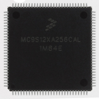
MC9S12XA256CAL Freescale Semiconductor, MC9S12XA256CAL Datasheet - Page 1268

MC9S12XA256CAL
Manufacturer Part Number
MC9S12XA256CAL
Description
IC MCU 256K FLASH 112-LQFP
Manufacturer
Freescale Semiconductor
Series
HCS12r
Specifications of MC9S12XA256CAL
Core Processor
HCS12X
Core Size
16-Bit
Speed
80MHz
Connectivity
EBI/EMI, I²C, IrDA, LIN, SCI, SPI
Peripherals
LVD, POR, PWM, WDT
Number Of I /o
91
Program Memory Size
256KB (256K x 8)
Program Memory Type
FLASH
Eeprom Size
4K x 8
Ram Size
16K x 8
Voltage - Supply (vcc/vdd)
2.35 V ~ 5.5 V
Data Converters
A/D 16x10b
Oscillator Type
External
Operating Temperature
-40°C ~ 85°C
Package / Case
112-LQFP
No. Of I/o's
91
Eeprom Memory Size
4KB
Ram Memory Size
16KB
Cpu Speed
80MHz
No. Of Timers
1
No. Of Pwm Channels
8
Digital Ic Case Style
LQFP
Rohs Compliant
Yes
Processor Series
S12XA
Core
HCS12
Data Bus Width
16 bit
Data Ram Size
16 KB
Interface Type
CAN, I2C, SCI, SPI
Maximum Clock Frequency
40 MHz
Number Of Programmable I/os
91
Number Of Timers
12
Maximum Operating Temperature
+ 85 C
Mounting Style
SMD/SMT
3rd Party Development Tools
EWHCS12
Development Tools By Supplier
EVB9S12XDP512E
Minimum Operating Temperature
- 40 C
On-chip Adc
2 (10 bit, 16 Channel)
Package
112LQFP
Family Name
HCS12
Maximum Speed
40 MHz
Operating Supply Voltage
2.5|5 V
Lead Free Status / RoHS Status
Lead free / RoHS Compliant
Available stocks
Company
Part Number
Manufacturer
Quantity
Price
Company:
Part Number:
MC9S12XA256CAL
Manufacturer:
AD
Quantity:
101
Company:
Part Number:
MC9S12XA256CAL
Manufacturer:
Freescale Semiconductor
Quantity:
10 000
Part Number:
MC9S12XA256CAL
Manufacturer:
FREESCALE
Quantity:
20 000
- Current page: 1268 of 1348
- Download datasheet (8Mb)
Appendix A Electrical Characteristics
A.5.3
The oscillator provides the reference clock for the PLL. The PLL´s voltage controlled oscillator (VCO) is
also the system clock source in self clock mode.
A.5.3.1
This section describes the selection of the XFC components to achieve a good filter characteristics.
The following procedure can be used to calculate the resistance and capacitance values using typical values
for K
The grey boxes show the calculation for f
are used for f
The VCO gain at the desired VCO frequency is approximated by:
The phase detector relationship is given by:
i
The loop bandwidth f
typical values are 50. = 0.9 ensures a good transient response.
1270
ch
is the current in tracking mode.
1
, f
1
f
and i
osc
Phase Locked Loop
OSC
XFC Component Selection
ch
from
= 4-MHz and a 40-MHz bus clock.
K
refdv+1
V
C
1
Table
=
should be chosen to fulfill the Gardner’s stability criteria by at least a factor of 10,
K
K
1
A-23.
f
e
=
ref
--------------------------- -
f 1 f vco
Figure A-3. Basic PLL Functional Diagram
–
K 1 1V
V
i
DDPLL
–
ch
MC9S12XDP512 Data Sheet, Rev. 2.21
K
V
D
VCO
fcmp
=
C
–
p
C
=
= 80 MHz and f
3.5 A
s
Detector
–
Loop Divider
Phase
195MHz V
synr+1
KF
1
R
–
154MHz
e
ref
126 80
------------------- -
–
V
= 4 MHz. For example, these frequencies
195
XFC Pin
–
=
539.1Hz
1
2
= -154.0MHz/V
VCO
KV
Freescale Semiconductor
f
vco
Related parts for MC9S12XA256CAL
Image
Part Number
Description
Manufacturer
Datasheet
Request
R
Part Number:
Description:
Manufacturer:
Freescale Semiconductor, Inc
Datasheet:
Part Number:
Description:
Manufacturer:
Freescale Semiconductor, Inc
Datasheet:
Part Number:
Description:
Manufacturer:
Freescale Semiconductor, Inc
Datasheet:
Part Number:
Description:
Manufacturer:
Freescale Semiconductor, Inc
Datasheet:
Part Number:
Description:
Manufacturer:
Freescale Semiconductor, Inc
Datasheet:
Part Number:
Description:
Manufacturer:
Freescale Semiconductor, Inc
Datasheet:
Part Number:
Description:
Manufacturer:
Freescale Semiconductor, Inc
Datasheet:
Part Number:
Description:
Manufacturer:
Freescale Semiconductor, Inc
Datasheet:
Part Number:
Description:
Manufacturer:
Freescale Semiconductor, Inc
Datasheet:
Part Number:
Description:
Manufacturer:
Freescale Semiconductor, Inc
Datasheet:
Part Number:
Description:
Manufacturer:
Freescale Semiconductor, Inc
Datasheet:
Part Number:
Description:
Manufacturer:
Freescale Semiconductor, Inc
Datasheet:
Part Number:
Description:
Manufacturer:
Freescale Semiconductor, Inc
Datasheet:
Part Number:
Description:
Manufacturer:
Freescale Semiconductor, Inc
Datasheet:
Part Number:
Description:
Manufacturer:
Freescale Semiconductor, Inc
Datasheet:


