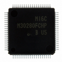
M30280FCHP#U5B Renesas Electronics America, M30280FCHP#U5B Datasheet - Page 15

M30280FCHP#U5B
Manufacturer Part Number
M30280FCHP#U5B
Description
IC M16C/28 MCU FLASH 128K 80LQFP
Manufacturer
Renesas Electronics America
Series
M16C™ M16C/Tiny/28r
Datasheet
1.M30280F6HPU9.pdf
(425 pages)
Specifications of M30280FCHP#U5B
Core Processor
M16C/60
Core Size
16-Bit
Speed
20MHz
Connectivity
I²C, IEBus, SIO, UART/USART
Peripherals
DMA, POR, PWM, Voltage Detect, WDT
Number Of I /o
71
Program Memory Size
128KB (128K x 8)
Program Memory Type
FLASH
Ram Size
12K x 8
Voltage - Supply (vcc/vdd)
2.7 V ~ 5.5 V
Data Converters
A/D 24x10b
Oscillator Type
Internal
Operating Temperature
-20°C ~ 85°C
Package / Case
80-LQFP
For Use With
R0K330290S000BE - KIT EVAL STARTER FOR M16C/29M30290T2-CPE - EMULATOR COMPACT M16C/26A/28/29M30290T2-CPE-HP - EMULATOR COMPACT FOR M16C/TINY
Lead Free Status / RoHS Status
Lead free / RoHS Compliant
Eeprom Size
-
Available stocks
Company
Part Number
Manufacturer
Quantity
Price
Part Number:
M30280FCHP#U5BM30280FCHP#U3B
Manufacturer:
Renesas Electronics America
Quantity:
10 000
Part Number:
M30280FCHP#U5BM30280FCHP#U7B
Manufacturer:
Renesas Electronics America
Quantity:
10 000
- Current page: 15 of 425
- Download datasheet (4Mb)
17. Programmable I/O Ports ............................................................................282
18. Flash Memory Version ...............................................................................296
16.7 I
16.8 I
16.9 START Condition Generation Method ....................................................................... 273
16.10 START Condition Duplicate Protect Function ........................................................... 274
16.11 STOP Condition Generation Method ........................................................................ 274
16.12 START/STOP Condition Detect Operation ............................................................... 276
16.13 Address Data Communication ................................................................................. 277
16.14 Precautions ............................................................................................................... 279
17.1 Port Pi Direction Register (PDi Register, i = 0 to 3, 6 to 10) ....................................... 282
17.2 Port Pi Register (Pi Register, i = 0 to 3, 6 to 10) ......................................................... 282
17.3 Pull-up Control Register 0 to 2 (PUR0 to PUR2 Registers) ........................................ 282
17.4 Port Control Register (PCR Register) ......................................................................... 282
17.5 Pin Assignment Control Register (PACR) ................................................................... 283
17.6 Digital Debounce Function ......................................................................................... 283
18.1 Flash Memory Performance ....................................................................................... 296
18.2 Memory Map ............................................................................................................... 298
18.3 Functions To Prevent Flash Memory from Rewriting .................................................. 302
16.6.4 Bits 4,5 : SDA/SCL Logic Output Value Monitor Bits SDAM/SCLM .................... 269
16.6.5 Bits 6,7 : I
16.6.6 Address Receive in STOP/WAIT Mode ............................................................... 269
16.7.1 Bit0: Time-Out Detection Function Enable Bit (TOE) .......................................... 271
16.7.2 Bit1: Time-Out Detection Flag (TOF ).................................................................. 271
16.7.3 Bit2: Time-Out Detection Period Select Bit (TOSEL) .......................................... 271
16.7.4 Bits 3,4,5: I
16.7.5 Bit7: STOP Condition Detection Interrupt Request Bit (SCPIN).......................... 271
16.8.1 Bit0-Bit4: START/STOP Condition Setting Bits (SSC0-SSC4) ............................ 272
16.8.2 Bit5: SCL/SDA Interrupt Pin Polarity Select Bit (SIP) .......................................... 272
16.8.3 Bit6 : SCL/SDA Interrupt Pin Select Bit (SIS) ...................................................... 272
16.8.4 Bit7: START/STOP Condition Generation Select Bit (STSPSEL) ....................... 272
16.13.1 Example of Master Transmit ............................................................................. 277
16.13.2 Example of Slave Receive ................................................................................ 278
18.1.1 Boot Mode ........................................................................................................... 297
18.3.1 ROM Code Protect Function ................................................................................ 302
18.3.2 ID Code Check Function ...................................................................................... 302
2
2
C0 Control Register 2 (S4D0 Register) ................................................................... 270
C0 START/STOP Condition Control Register (S2D0 Register) ............................... 272
2
C System Clock Select Bits ICK0, ICK1 ............................................ 269
2
C System Clock Select Bits (ICK2-4) ............................................... 271
A-6
Related parts for M30280FCHP#U5B
Image
Part Number
Description
Manufacturer
Datasheet
Request
R

Part Number:
Description:
KIT STARTER FOR M16C/29
Manufacturer:
Renesas Electronics America
Datasheet:

Part Number:
Description:
KIT STARTER FOR R8C/2D
Manufacturer:
Renesas Electronics America
Datasheet:

Part Number:
Description:
R0K33062P STARTER KIT
Manufacturer:
Renesas Electronics America
Datasheet:

Part Number:
Description:
KIT STARTER FOR R8C/23 E8A
Manufacturer:
Renesas Electronics America
Datasheet:

Part Number:
Description:
KIT STARTER FOR R8C/25
Manufacturer:
Renesas Electronics America
Datasheet:

Part Number:
Description:
KIT STARTER H8S2456 SHARPE DSPLY
Manufacturer:
Renesas Electronics America
Datasheet:

Part Number:
Description:
KIT STARTER FOR R8C38C
Manufacturer:
Renesas Electronics America
Datasheet:

Part Number:
Description:
KIT STARTER FOR R8C35C
Manufacturer:
Renesas Electronics America
Datasheet:

Part Number:
Description:
KIT STARTER FOR R8CL3AC+LCD APPS
Manufacturer:
Renesas Electronics America
Datasheet:

Part Number:
Description:
KIT STARTER FOR RX610
Manufacturer:
Renesas Electronics America
Datasheet:

Part Number:
Description:
KIT STARTER FOR R32C/118
Manufacturer:
Renesas Electronics America
Datasheet:

Part Number:
Description:
KIT DEV RSK-R8C/26-29
Manufacturer:
Renesas Electronics America
Datasheet:

Part Number:
Description:
KIT STARTER FOR SH7124
Manufacturer:
Renesas Electronics America
Datasheet:

Part Number:
Description:
KIT STARTER FOR H8SX/1622
Manufacturer:
Renesas Electronics America
Datasheet:

Part Number:
Description:
KIT DEV FOR SH7203
Manufacturer:
Renesas Electronics America
Datasheet:


