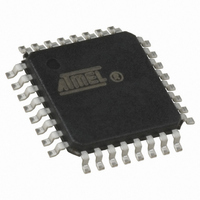
AT90LS2333-4AI Atmel, AT90LS2333-4AI Datasheet - Page 28

AT90LS2333-4AI
Manufacturer Part Number
AT90LS2333-4AI
Description
IC MCU 2K 4MHZ A/D LV IT 32TQFP
Manufacturer
Atmel
Series
AVR® 90LSr
Datasheet
1.AT90LS2333-4AC.pdf
(103 pages)
Specifications of AT90LS2333-4AI
Core Processor
AVR
Core Size
8-Bit
Speed
4MHz
Connectivity
SPI, UART/USART
Peripherals
Brown-out Detect/Reset, POR, PWM, WDT
Number Of I /o
20
Program Memory Size
2KB (1K x 16)
Program Memory Type
FLASH
Eeprom Size
128 x 8
Ram Size
128 x 8
Voltage - Supply (vcc/vdd)
2.7 V ~ 6 V
Data Converters
A/D 6x10b
Oscillator Type
Internal
Operating Temperature
-40°C ~ 85°C
Package / Case
32-TQFP, 32-VQFP
Lead Free Status / RoHS Status
Contains lead / RoHS non-compliant
Timer / Counters
The AT90S2333/4433 provides two general purpose Timer/Counters - one 8-bit T/C and one 16-bit T/C. Timer/Counters 0
and 1 have individual prescaling selection from the same 10-bit prescaling timer. These Timer/Counters can either be used
as a timer with an internal clock timebase or as a counter with an external pin connection which triggers the counting.
Timer/Counter Prescaler
Figure 30. Prescaler for Timer/Counter0 and 1
TCK1
TCK0
For Timer/Counters 0 and 1, the four different prescaled selections are: CK/8, CK/64, CK/256 and CK/1024, where CK is
the oscillator clock. For the two Timer/Counters 0 and 1, external source and stop can also be selected as clock sources.
8-bit Timer/Counter0
The 8-bit Timer/Counter0 can select clock source from CK, prescaled CK, or an external pin. In addition it can be stopped
as described in the specification for the Timer/Counter0 Control Register - TCCR0. The overflow status flag is found in the
Timer/Counter Interrupt Flag Register - TIFR. Control signals are found in the Timer/Counter0 Control Register - TCCR0.
The interrupt enable/disable settings for Timer/Counter0 are found in the Timer/Counter Interrupt Mask Register - TIMSK.
When Timer/Counter0 is externally clocked, the external signal is synchronized with the oscillator frequency of the CPU. To
assure proper sampling of the external clock, the minimum time between two external clock transitions must be at least one
internal CPU clock period. The external clock signal is sampled on the rising edge of the internal CPU clock.
The 8-bit Timer/Counter0 features both a high resolution and a high accuracy usage with the lower prescaling opportuni-
ties. Similarly, the high prescaling opportunities make the Timer/Counter0 useful for lower speed functions or exact timing
functions with infrequent actions. Figure 31 shows the block diagram for Timer/Counter0.
AT90S/LS2333 and AT90S/LS4433
28


