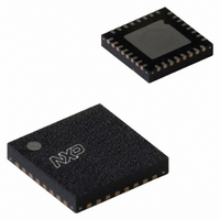
MFRC52301HN1,151 NXP Semiconductors, MFRC52301HN1,151 Datasheet - Page 32

MFRC52301HN1,151
Manufacturer Part Number
MFRC52301HN1,151
Description
IC MIFARE READER 32-HVQFN
Manufacturer
NXP Semiconductors
Series
MIFARE®r
Specifications of MFRC52301HN1,151
Frequency
13.56MHz
Package / Case
32-VQFN Exposed Pad, 32-HVQFN, 32-SQFN, 32-DHVQFN
Operating Current
7 mA
Operating Voltage
2.5 V to 3.6 V
Product
RFID Readers
Wireless Frequency
13.56 MHz
Interface Type
RS-232, I2C
Data Rate
100 Kbps
Operating Temperature Range
- 25 C to +85 C
Lead Free Status / RoHS Status
Lead free / RoHS Compliant
Features
-
Rf Type
-
Lead Free Status / RoHS Status
Lead free / RoHS Compliant
Other names
568-4766
935282956151
MFRC52301HN1
935282956151
MFRC52301HN1
NXP Semiconductors
MFRC523_32
Product data sheet
PUBLIC
8.8.1 Hard power-down
8.8.2 Soft power-down mode
8.8.3 Transmitter power-down mode
8.8 Power reduction modes
8.9 Oscillator circuitry
Hard power-down is enabled when pin NRSTPD is LOW. This turns off all internal current
sinks including the oscillator. All digital input buffers are separated from the input pins and
clamped internally (except pin NRSTPD). The output pins are frozen at either a HIGH or
LOW level.
Soft Power-down mode is entered immediately after the CommandReg register’s
PowerDown bit is set to logic 1. All internal current sinks are switched off, including the
oscillator buffer. However, the digital input buffers are not separated from the input pins
and keep their functionality. The digital output pins do not change their state.
During soft power-down, all register values, the FIFO buffer content and the configuration
keep their current contents.
After setting the PowerDown bit to logic 0, it takes 1024 clocks until the Soft power-down
mode is exited indicated by the PowerDown bit. Setting it to logic 0 does not immediately
clear it. It is cleared automatically by the MFRC523 when Soft power-down mode is
exited.
Remark: If the internal oscillator is used, you must take into account that it is supplied by
pin AVDD and it will take a certain time (t
cycles can be detected by the internal logic. It is recommended for the serial UART, to first
send the value 55h to the MFRC523. The oscillator must be stable for further access to
the registers. To ensure this, perform a read access to address 0 until the MFRC523
answers to the last read command with the register content of address 0. This indicates
that the MFRC523 is ready.
The Transmitter Power-down mode switches off the internal antenna drivers thereby,
turning off the RF field. Transmitter power-down mode is entered by setting either the
TxControlReg register’s Tx1RFEn bit or Tx2RFEn bit to logic 0.
Fig 22. Quartz crystal connection
Rev. 3.2 — 12 January 2010
115232
OSCOUT
MFRC523
osc
27.12 MHz
) until the oscillator is stable and the clock
OSCIN
001aal162
Contactless reader IC
MFRC523
© NXP B.V. 2010. All rights reserved.
32 of 98


