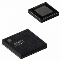
MFRC52301HN1,151 NXP Semiconductors, MFRC52301HN1,151 Datasheet - Page 33

MFRC52301HN1,151
Manufacturer Part Number
MFRC52301HN1,151
Description
IC MIFARE READER 32-HVQFN
Manufacturer
NXP Semiconductors
Series
MIFARE®r
Specifications of MFRC52301HN1,151
Frequency
13.56MHz
Package / Case
32-VQFN Exposed Pad, 32-HVQFN, 32-SQFN, 32-DHVQFN
Operating Current
7 mA
Operating Voltage
2.5 V to 3.6 V
Product
RFID Readers
Wireless Frequency
13.56 MHz
Interface Type
RS-232, I2C
Data Rate
100 Kbps
Operating Temperature Range
- 25 C to +85 C
Lead Free Status / RoHS Status
Lead free / RoHS Compliant
Features
-
Rf Type
-
Lead Free Status / RoHS Status
Lead free / RoHS Compliant
Other names
568-4766
935282956151
MFRC52301HN1
935282956151
MFRC52301HN1
NXP Semiconductors
MFRC523_32
Product data sheet
PUBLIC
8.10.1 Reset timing requirements
8.10.2 Oscillator start-up time
8.10 Reset and oscillator start-up time
The clock applied to the MFRC523 provides a time basis for the synchronous system’s
encoder and decoder. The stability of the clock frequency, therefore, is an important factor
for correct operation. To obtain optimum performance, clock jitter must be reduced as
much as possible. This is best achieved using the internal oscillator buffer with the
recommended circuitry.
If an external clock source is used, the clock signal must be applied to pin OSCIN. In this
case, special care must be taken with the clock duty cycle and clock jitter and the clock
quality must be verified.
The reset signal is filtered by a hysteresis circuit and a spike filter before it enters the
digital circuit. The spike filter rejects signals shorter than 10 ns. In order to perform a
reset, the signal must be LOW for at least 100 ns.
If the MFRC523 has been set to a Power-down mode or is powered by a V
start-up time for the MFRC523 depends on the oscillator used and is shown in
The time (t
start-up time is defined by the crystal.
The time (t
before the MFRC523 can be addressed.
The delay time is calculated by:
The time (t
t
d
Fig 23. Oscillator start-up time
=
device activation
------------- -
27 s
1024
clock stable
clock ready
oscillator
startup
d
osc
) is the internal delay time of the MFRC523 when the clock signal is stable
=
) is the sum of t
37.74 s
) is the start-up time of the crystal oscillator circuit. The crystal oscillator
Rev. 3.2 — 12 January 2010
d
115232
and t
startup
.
t
startup
t
osc
Contactless reader IC
MFRC523
© NXP B.V. 2010. All rights reserved.
t
d
DDX
001aak596
supply, the
Figure
33 of 98
t
23.
(6)


