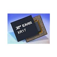
XR17V258IV-F Exar Corporation, XR17V258IV-F Datasheet - Page 19

XR17V258IV-F
Manufacturer Part Number
XR17V258IV-F
Description
IC UART PCI BUS OCTAL 144LQFP
Manufacturer
Exar Corporation
Type
Octal UARTr
Datasheet
1.XR17V258IVTR-F.pdf
(69 pages)
Specifications of XR17V258IV-F
Number Of Channels
8
Package / Case
144-LQFP
Features
*
Fifo's
64 Byte
Protocol
RS485
Voltage - Supply
3.3V, 5V
With Auto Flow Control
Yes
With Irda Encoder/decoder
Yes
With False Start Bit Detection
Yes
With Modem Control
Yes
Mounting Type
Surface Mount
Data Rate
8 Mbps
Supply Voltage (max)
3.6 V
Supply Voltage (min)
3 V
Supply Current
4 mA
Maximum Operating Temperature
+ 85 C
Minimum Operating Temperature
- 45 C
Mounting Style
SMD/SMT
Operating Supply Voltage
3 V to 3.6 V
No. Of Channels
8
Uart Features
Tx/Rx FIFO Counters
Supply Voltage Range
3V To 3.6V
Operating Temperature Range
-40°C To +85°C
Digital Ic Case Style
LQFP
No. Of Pins
144
Rohs Compliant
Yes
Lead Free Status / RoHS Status
Lead free / RoHS Compliant
Lead Free Status / RoHS Status
Lead free / RoHS Compliant, Lead free / RoHS Compliant
Available stocks
Company
Part Number
Manufacturer
Quantity
Price
Company:
Part Number:
XR17V258IV-F
Manufacturer:
EXAR
Quantity:
295
Company:
Part Number:
XR17V258IV-F
Manufacturer:
Exar Corporation
Quantity:
10 000
Part Number:
XR17V258IV-F
Manufacturer:
EXAR/艾科嘉
Quantity:
20 000
REV. 1.0.2
.
F
Wake-up Indicator is cleared by reading the INT0 register.
RXRDY and RXRDY Time-out is cleared by reading data in the RX FIFO until the RX FIFO is empty.
RX Line Status interrupt clears after reading the LSR register that is in the UART channel register set.
TXRDY interrupt clears after reading ISR register that is in the UART channel register set.
Modem Status Register interrupt clears after reading MSR register that is in the UART channel register set.
RTS/CTS or DTR/DSR delta interrupt clears after reading MSR register that is in the UART channel register set.
Xoff/Xon delta and special character detect interrupt clears after reading the ISR register that is in the UART channel reg-
ister set.
TIMER Time-out interrupt clears after reading the TIMERCNTL register that is in the Device Configuration register set.
MPIO interrupt clears after reading the MPIOLVL register that is in the Device Configuration register set.
P
IGURE
RIORITY
N+2
Bit
1
2
3
4
5
6
7
x
Channel-7
N+1
5. T
Bit
B
Bit
HE
N
IT
[
0
0
0
0
1
1
1
1
N
INT3 Register
G
N+2
+2]
Bit
LOBAL
Channel-6
N+1
Bit
B
IT
I
T
[
Bit
NTERRUPT
N
0
0
1
1
0
0
1
1
N
ABLE
+1]
N+2
Bit
T
ABLE
Channel-5
8: UART C
N+1
66MHZ PCI BUS OCTAL UART WITH POWER MANAGEMENT SUPPORT
Bit
B
IT
0
1
0
1
0
1
0
1
R
9: UART C
[
N
EGISTER
Bit
N
]
N+2
Bit
None or wake-up indicator
RXRDY and RX Line Status (logic OR of LSR[4:1])
RXRDY Time-out
TXRDY, THR or TSR (auto RS485 mode) empty
MSR, RTS/CTS or DTR/DSR delta or Xoff/Xon det. or special char. detected
Reserved.
MPIO pin(s). Available only within channel 0, reserved in other channels.
TIMER Time-out. Available only within channel 0, reserved in other chan-
nels.
HANNEL
Channel-4
INT0, INT1, INT2 and INT3
N+1
, INT0, INT1, INT2
Bit
HANNEL
Interrupt Registers,
INT2 Register
Bit
N
[7:0] I
N+2
Bit
19
[7:0] I
Channel-3
NTERRUPT
N+1
Bit
NTERRUPT
Bit
N
AND
N+2
I
Bit
NTERRUPT
S
Channel-2
INT3
OURCE
Ch-7 Ch-6 Ch-5 Ch-4
N+1
Bit-7
Bit
C
LEARING
Bit-6
Bit
N
E
S
NCODING
OURCE
Bit-5
N+2
Bit
Channel-1
INT0 Register
Bit-4
N+1
INT1 Register
Bit
(
S
)
Ch-3 Ch-2 Ch-1 Ch-0
Bit-3
Bit
N
N+2
Bit-2
Bit
Channel-0
N+1
Bit-1
XR17V258
Bit
Bit-0
Bit
N


