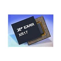
XR17V258IV-F Exar Corporation, XR17V258IV-F Datasheet - Page 27

XR17V258IV-F
Manufacturer Part Number
XR17V258IV-F
Description
IC UART PCI BUS OCTAL 144LQFP
Manufacturer
Exar Corporation
Type
Octal UARTr
Datasheet
1.XR17V258IVTR-F.pdf
(69 pages)
Specifications of XR17V258IV-F
Number Of Channels
8
Package / Case
144-LQFP
Features
*
Fifo's
64 Byte
Protocol
RS485
Voltage - Supply
3.3V, 5V
With Auto Flow Control
Yes
With Irda Encoder/decoder
Yes
With False Start Bit Detection
Yes
With Modem Control
Yes
Mounting Type
Surface Mount
Data Rate
8 Mbps
Supply Voltage (max)
3.6 V
Supply Voltage (min)
3 V
Supply Current
4 mA
Maximum Operating Temperature
+ 85 C
Minimum Operating Temperature
- 45 C
Mounting Style
SMD/SMT
Operating Supply Voltage
3 V to 3.6 V
No. Of Channels
8
Uart Features
Tx/Rx FIFO Counters
Supply Voltage Range
3V To 3.6V
Operating Temperature Range
-40°C To +85°C
Digital Ic Case Style
LQFP
No. Of Pins
144
Rohs Compliant
Yes
Lead Free Status / RoHS Status
Lead free / RoHS Compliant
Lead Free Status / RoHS Status
Lead free / RoHS Compliant, Lead free / RoHS Compliant
Available stocks
Company
Part Number
Manufacturer
Quantity
Price
Company:
Part Number:
XR17V258IV-F
Manufacturer:
EXAR
Quantity:
295
Company:
Part Number:
XR17V258IV-F
Manufacturer:
Exar Corporation
Quantity:
10 000
Part Number:
XR17V258IV-F
Manufacturer:
EXAR/艾科嘉
Quantity:
20 000
REV. 1.0.2
MPIO3T [7:0] (default 0x00)
The MPIO outputs can be tri-stated by the MPIO3T register. A logic 0 (default) sets the output to active level
per register MPIOBIT settling, a logic 1 sets the output pin to tri-state.
MPIOINV [7:0] (default 0x00)
The MPIO inputs can be inverted by the MPIOINV register. A logic 0 (default) does not invert the input pin logic.
A logic 1 inverts the input logic level.
MPIOSEL [7:0] (default 0xFF)
The MPIOSEL register defines the MPIOs as either an input or output. A logic 1 (default) defines the pin for
input and a logic 0 for output.
The V258 includes an on-chip oscillator (XTAL1 and XTAL2). The crystal oscillator provides the system clock
to the Baud Rate Generators (BRG) in each of the 8 UARTs, the 16-bit general purpose timer/counter and
internal logics. XTAL1 is the input to the oscillator or external clock buffer input with XTAL2 pin being the
output. See the Programmable Baud Rate Generator in the UART section on
The on-chip oscillator is designed to use an industry standard microprocessor crystal (parallel resonant with
10-22 pF capacitance load, 100ppm) connected externally between the XTAL1 and XTAL2 pins (see
Figure 10
2.0 CRYSTAL OSCILLATOR / BUFFER
). Alternatively, an external clock can be connected to the XTAL1 pin to clock the internal 8 baud rate
66MHZ PCI BUS OCTAL UART WITH POWER MANAGEMENT SUPPORT
MPIO7
Bit-7 Bit-6 Bit-5 Bit-4 Bit-3 Bit-2 Bit-1 Bit-0
Bit-7 Bit-6 Bit-5 Bit-4 Bit-3 Bit-2 Bit-1 Bit-0
MPIO7
Bit-7 Bit-6 Bit-5 Bit-4 Bit-3 Bit-2 Bit-1 Bit-0
MPIO7
Bit-7 Bit-6 Bit-5 Bit-4 Bit-3 Bit-2 Bit-1 Bit-0
MPIO7
Multipurpose Input Signal Inversion Enable
MPIO6
Multipurpose Input/Output Selection
MPIO6
MPIO6
MPIO6
Multipurpose Output Level Control
Multipurpose Output 3-state Enable
MPIO5 MPIO4 MPIO3 MPIO2 MPIO1 MPIO0
MPIO5 MPIO4 MPIO3 MPIO2 MPIO1 MPIO0
MPIO5 MPIO4 MPIO3 MPIO2 MPIO1 MPIO0
MPIO5 MPIO4 MPIO3 MPIO2 MPIO1 MPIO0
MPIOSEL Register
MPIOLVL Register
MPIOINV Register
MPIO3T Register
27
page 31
for programming details.
XR17V258


