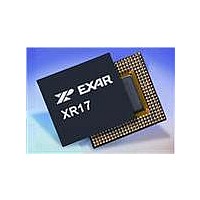
XR17V258IV-F Exar Corporation, XR17V258IV-F Datasheet - Page 55

XR17V258IV-F
Manufacturer Part Number
XR17V258IV-F
Description
IC UART PCI BUS OCTAL 144LQFP
Manufacturer
Exar Corporation
Type
Octal UARTr
Datasheet
1.XR17V258IVTR-F.pdf
(69 pages)
Specifications of XR17V258IV-F
Number Of Channels
8
Package / Case
144-LQFP
Features
*
Fifo's
64 Byte
Protocol
RS485
Voltage - Supply
3.3V, 5V
With Auto Flow Control
Yes
With Irda Encoder/decoder
Yes
With False Start Bit Detection
Yes
With Modem Control
Yes
Mounting Type
Surface Mount
Data Rate
8 Mbps
Supply Voltage (max)
3.6 V
Supply Voltage (min)
3 V
Supply Current
4 mA
Maximum Operating Temperature
+ 85 C
Minimum Operating Temperature
- 45 C
Mounting Style
SMD/SMT
Operating Supply Voltage
3 V to 3.6 V
No. Of Channels
8
Uart Features
Tx/Rx FIFO Counters
Supply Voltage Range
3V To 3.6V
Operating Temperature Range
-40°C To +85°C
Digital Ic Case Style
LQFP
No. Of Pins
144
Rohs Compliant
Yes
Lead Free Status / RoHS Status
Lead free / RoHS Compliant
Lead Free Status / RoHS Status
Lead free / RoHS Compliant, Lead free / RoHS Compliant
Available stocks
Company
Part Number
Manufacturer
Quantity
Price
Company:
Part Number:
XR17V258IV-F
Manufacturer:
EXAR
Quantity:
295
Company:
Part Number:
XR17V258IV-F
Manufacturer:
Exar Corporation
Quantity:
10 000
Part Number:
XR17V258IV-F
Manufacturer:
EXAR/艾科嘉
Quantity:
20 000
REV. 1.0.2
FCTR[4]: Infrared RX Input Logic Select
•
•
FCTR [3:0] - Auto RTS/DTR Flow Control Hysteresis Select
These bits select the auto RTS/DTR flow control hysteresis and only valid when TX and RX Trigger Table-D is
selected (FCTR bit [7:6] are set to logic 1). The RTS/DTR hysteresis is referenced to the RX FIFO trigger level.
After reset, these bits are set to logic 0 selecting the next FIFO trigger level for hardware flow control.
below shows the 16 selectable hysteresis levels.
Enhanced features are enabled or disabled using this register. Bits [3:0] provide single or dual consecutive
character software flow control selection (see
are selected, the double 8-bit words are concatenated into two sequential characters. Caution: note that
whenever changing the TX or RX flow control bits, always reset all bits back to logic 0 (disable) before
programming a new setting.
EFR[7]: Auto CTS Flow Control Enable
Automatic CTS or DSR Flow Control.
•
•
5.14
Logic 0 = Select RX input as active HIGH encoded IrDA data, normal, (default).
Logic 1 = Select RX input as active LOW encoded IrDA data, inverted.
Logic 0 = Automatic CTS/DSR flow control is disabled (default).
Logic 1 = Enable Automatic CTS/DSR flow control. Transmission stops when CTS/DSR# pin de-asserts
(HIGH). Transmission resumes when CTS/DSR# pin is asserted (LOW). The selection for CTS# or DSR# is
through MCR bit [2].
Enhanced Feature Register (EFR) - Read/Write
FCTR B
T
ABLE
0
0
0
0
0
0
0
0
1
1
1
1
1
1
1
1
IT
[3]
20: 16 S
FCTR B
ELECTABLE
0
0
0
0
1
1
1
1
1
1
1
1
0
0
0
0
66MHZ PCI BUS OCTAL UART WITH POWER MANAGEMENT SUPPORT
IT
[2]
H
YSTERESIS
FCTR B
Table 21
0
0
1
1
0
0
1
1
0
0
1
1
0
0
1
1
IT
L
[1]
EVELS
55
). When the Xon1 and Xon2 and Xoff1 and Xoff2 modes
W
FCTR B
HEN
0
1
0
1
0
1
0
1
0
1
0
1
0
1
0
1
T
RIGGER
IT
[0]
T
ABLE
RTS/DTR H
-D
(
CHARACTERS
IS
S
+/- 16
+/- 24
+/- 32
+/- 12
+/- 20
+/- 28
+/- 36
+/- 40
+/- 44
+/- 48
+/- 52
+/- 4
+/- 6
+/- 8
+/- 8
ELECTED
0
YSTERESIS
XR17V258
)
Table 20


