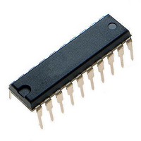
ATTINY461-20PU Atmel, ATTINY461-20PU Datasheet - Page 89

ATTINY461-20PU
Manufacturer Part Number
ATTINY461-20PU
Description
Microcontrollers (MCU) 4kB Flash 0.256kB EEPROM 16 I/O Pins
Manufacturer
Atmel
Specifications of ATTINY461-20PU
Processor Series
ATTINY4x
Core
AVR8
Data Bus Width
8 bit
Data Ram Size
256 B
Interface Type
2-Wire/SPI/USI
Maximum Clock Frequency
20 MHz
Number Of Programmable I/os
16
Number Of Timers
2
Operating Supply Voltage
4.5 V to 5.5 V
Maximum Operating Temperature
+ 85 C
Mounting Style
Through Hole
3rd Party Development Tools
EWAVR, EWAVR-BL
Development Tools By Supplier
ATAVRDRAGON, ATSTK500, ATSTK600, ATAVRISP2, ATAVRONEKIT
Minimum Operating Temperature
- 40 C
On-chip Adc
11-ch x 10-bit
Program Memory Type
Flash
Program Memory Size
4 KB
Package / Case
PDIP-20
Package
20PDIP
Device Core
AVR
Family Name
ATtiny
Maximum Speed
20 MHz
Ram Size
256 Byte
Operating Temperature
-40 to 85 °C
Lead Free Status / RoHS Status
Lead free / RoHS Compliant
- Current page: 89 of 242
- Download datasheet (5Mb)
12. Timer/Counter1
12.1
12.2
2588E–AVR–08/10
Features
Overview
•
•
•
•
•
•
•
•
•
Timer/Counter1 is a general purpose high speed Timer/Counter module, with three independent
Output Compare Units, and with PWM support.
The Timer/Counter1 features a high resolution and a high accuracy usage with the lower pres-
caling opportunities. It can also support three accurate and high speed Pulse Width Modulators
using clock speeds up to 64 MHz. In PWM mode Timer/Counter1 and the output compare regis-
ters serve as triple stand-alone PWMs with non-overlapping non-inverted and inverted outputs.
Similarly, the high prescaling opportunities make this unit useful for lower speed functions or
exact timing functions with infrequent actions. A simplified block diagram of the Timer/Counter1
is shown in
Figure 12-1. Timer/Counter1 Block Diagram
8/10-Bit Accuracy
Three Independent Output Compare Units
Clear Timer on Compare Match (Auto Reload)
Glitch Free, Phase and Frequency Correct Pulse Width Modulator (PWM)
Variable PWM Period
High Speed Asynchronous and Synchronous Clocking with Dedicated Prescaler
Independent Dead Time Generators for Each PWM Channel
Fault Protection Unit Can Disable PWM Output Pins
Five Independent Interrupt Sources (TOV1, OCF1A, OCD1B, OCF1D, FPF1)
TOV1
REGISTER (TIMSK)
T/C INT. MASK
TIMER/COUNTER1
8-BIT OUTPUT COMPARE
COMPARE REGISTER A
10-BIT COMPARATOR
REGISTER A (OCR1A)
(TCNT1)
OCF1A
10-BIT OUTPUT
Figure
OCF1B
REGISTER (TIFR)
12-1.
T/C INT. FLAG
CLK
COUNT
CLEAR
DIRECTION
OCF1D
10-BIT COMPARATOR
COMPARE REGISTER B
8-BIT OUTPUT COMPARE
REGISTER B (OCR1B)
10-BIT OUTPUT
DEAD TIME GENERATOR
OC1A
REGISTER A (TCCR1A)
T/C CONTROL
8-BIT DATABUS
OC1A
8-BIT OUTPUT COMPARE
COMPARE REGISTER C
10-BIT COMPARATOR
REGISTER C (OCR1C)
10-BIT OUTPUT
DEAD TIME GENERATOR
OC1B
REGISTER B (TCCR1B)
TIMER/COUNTER1 CONTROL LOGIC
T/C CONTROL
OC1B
8-BIT OUTPUT COMPARE
COMPARE REGISTER D
REGISTER D (OCR1D)
10-BIT COMPARATOR
10-BIT OUTPUT
REGISTER C (TCCR1C)
DEAD TIME GENERATOR
OC1D
T/C CONTROL
OC1D
2-BIT HIGH BYTE
REGISTER (TC1H)
REGISTER D (TCCR1E)
REGISTER C (TCCR1D)
FAULT_PROTECTION
T/C CONTROL
T/C CONTROL
89
Related parts for ATTINY461-20PU
Image
Part Number
Description
Manufacturer
Datasheet
Request
R

Part Number:
Description:
Manufacturer:
Atmel Corporation
Datasheet:

Part Number:
Description:
Manufacturer:
Atmel Corporation
Datasheet:

Part Number:
Description:
IC AVR MCU 4K 20MHZ 32-QFN
Manufacturer:
Atmel
Datasheet:

Part Number:
Description:
IC MCU AVR 4K FLASH 20MHZ 20SOIC
Manufacturer:
Atmel
Datasheet:

Part Number:
Description:
MCU AVR 4K FLASH 15MHZ 32-QFN
Manufacturer:
Atmel
Datasheet:

Part Number:
Description:
MCU AVR 4KB FLASH 15MHZ 32-VQFN
Manufacturer:
Atmel
Datasheet:

Part Number:
Description:
MCU AVR 4KB FLASH 20MHZ 20SOIC
Manufacturer:
Atmel
Datasheet:

Part Number:
Description:
IC MCU AVR 4K 20MHZ 32QFN
Manufacturer:
Atmel
Datasheet:

Part Number:
Description:
IC, MCU, 8BIT, 2K FLASH, 20SOIC
Manufacturer:
Atmel
Datasheet:

Part Number:
Description:
IC, MCU, 8BIT, 2K FLASH, 20PDIP
Manufacturer:
Atmel
Datasheet:


